4. INSTALLATION
14
– Connect the other end of the tube to the centralized draining point, checking the seal.
NOTE
MAKE SURE THE TUBE IS NOT BENT, CRUSHED OR OBSTRUCTED IN ANY WAY.
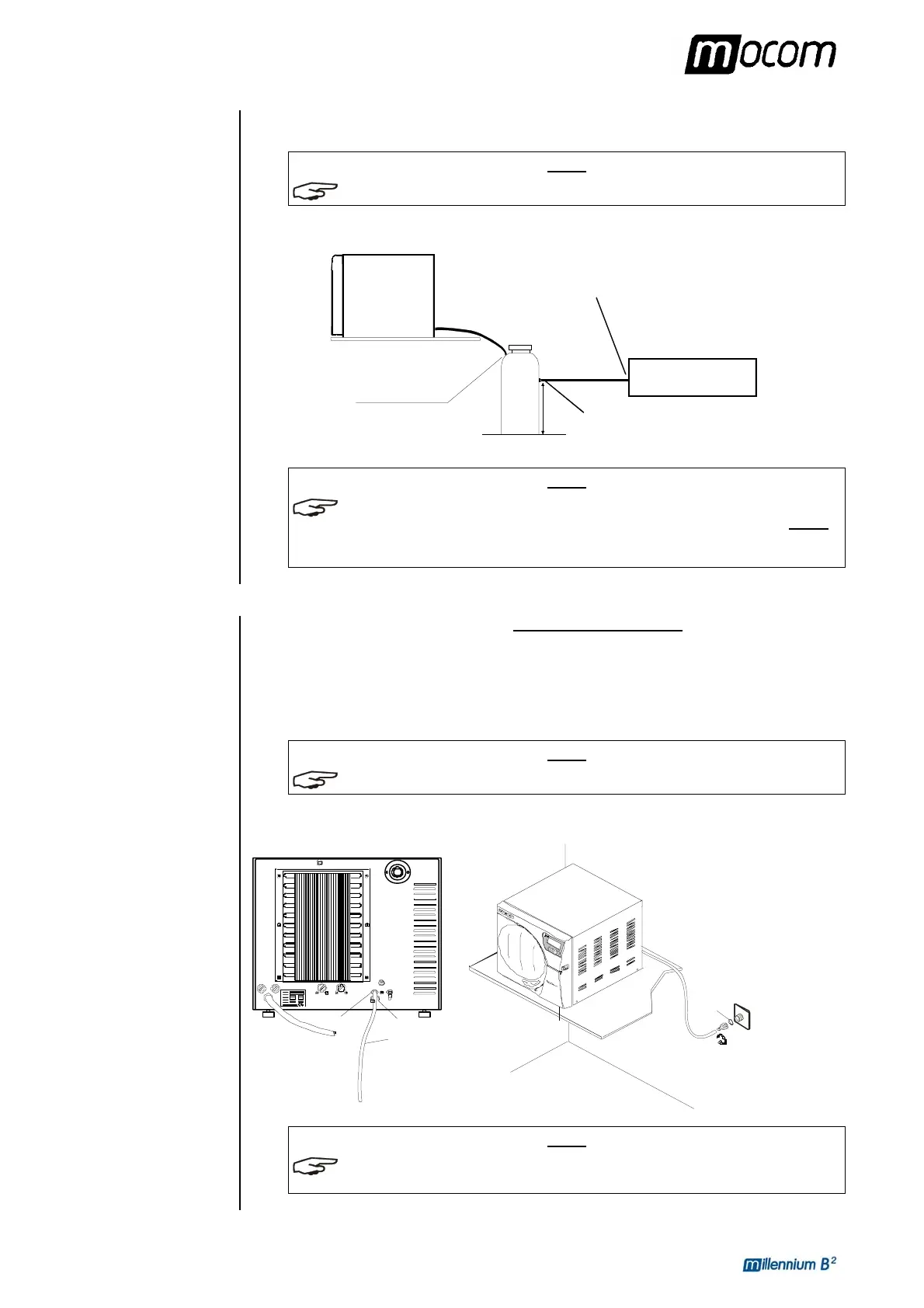
The following diagram provides an indicative arrangement of the components:
DRAIN
CENTRALIZED
Draining tank
Connection point
of the centralized draining plant
Connection point
of the draining tank
Sterilizer
X
Support plane
This point must be lower
than the support plane
NOTE
DIMENSION X IS THE HEIGHT OF THE SIDE CONNECTOR OF THE TANK ABOVE THE FLOOR.
THE CONNECTION BETWEEN THE TANK AND THE CENTRALIZED DRAINING POINT MUST
NO HIGHER THAN X
+30 MM. HIGHER CONNECTIONS COULD COMPROMISE THE CORRECT
EMPTYING OF THE TANK
.
DIRECT
CONNECTION TO A
CENTRALIZED
DRAINING POINT
Follow the instructions shown below for a correct direct connection to a centralized draining
point:
– Insert the silicone tube (provided) or other suitable plastic tube on hose union A; push the
tube all the way on and lock with the plastic tie or other means;
– Cut the tube to measure, push the free end on the connection provided on the centralized
draining point and lock with the plastic tie or other means;
NOTE
MAKE SURE THE TUBE IS NOT BENT, CRUSHED OR OBSTRUCTED IN ANY WAY.
The following diagram provides an indicative arrangement of the components:
A
Clip
Washer
Clip
Pipe
To the centralized
draining point
Centralized
draining point
Support plane
This point must be at level lower
than the sterilizer’s support plane
NOTE
THE CONNECTION POINT TO THE CENTRAL DRAIN MUST BE LOWER THAN THE
STERILIZER
'S SUPPORT SURFACE. OTHERWISE, THE TANK MAY NOT EMPTY CORRECTLY.