15.11.3 Fitlet2 - Screen Layout
The screen layout used for this option is identical to the TS12 console, but
the Fitlet2 option has the capability to show up to 498 zones. See "4.8 Zone
Display Options (TS12 Console)" on page 4-13 to view the screen layout.
NOTE
The Fitlet2 option allows users to store up to 120 images. Multiple images
can be associated with a single tool.
15.11.4 Fitlet2 - Upgrade Software
Software for the Fitlet2 option can be upgraded with the same procedure that
is used to upgrade M2 Plus controller software. See "8.1 Upgrade Software"
on page 8-1.
NOTE
For the Fitlet2 option, insert the USB memory stick with the software
upgrade into the USB port on the controller cabinet.
15.11.5 Fitlet2 - Connection
The Fitlet2 is connected to the user's external device via an Ethernet cable.
Ethernet port 1/2 on the Fitlet2 is specically congured for the customer. See
"Figure 15-1 Fitlet2 ports" on page 15-1.
1. Insert an Ethernet cable into the precongured Ethernet port.
2. Connect the Fitlet2 to the display device.
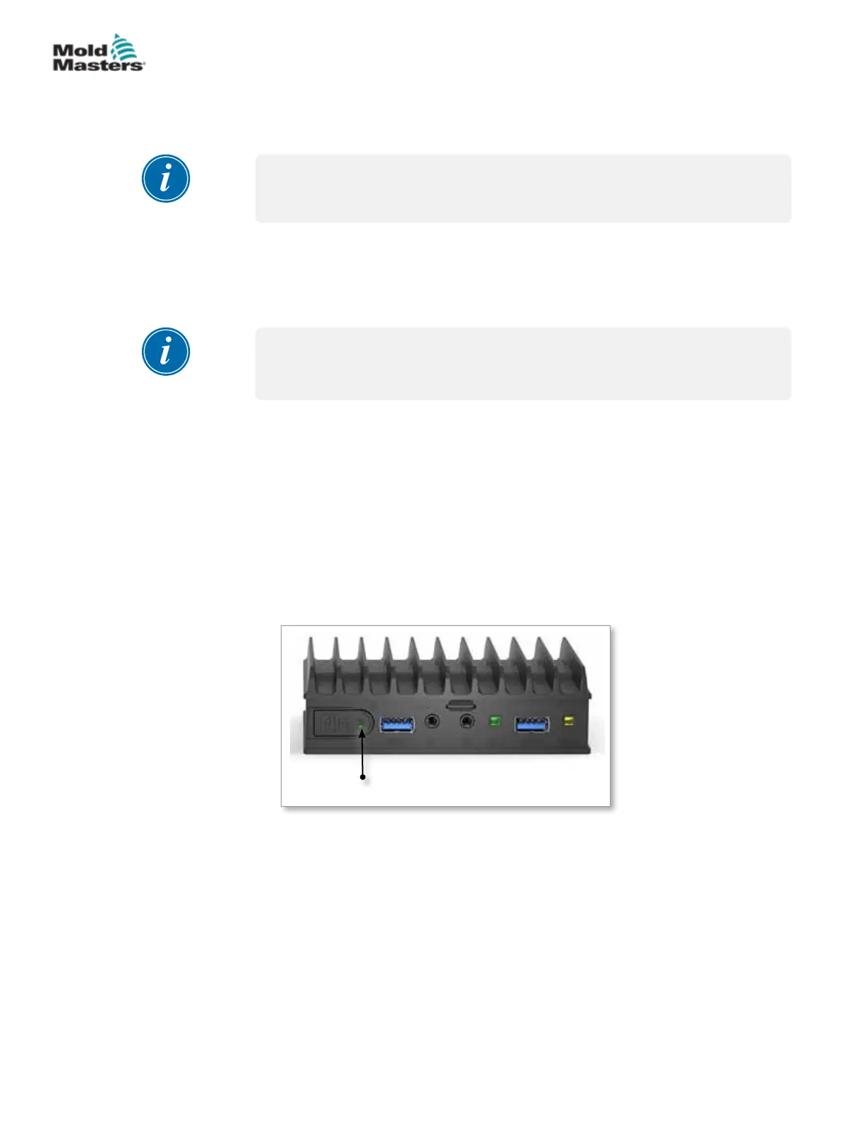
• Ensure the Fitlet2 is powered up. A green light at the front of the
device indicates that the Fitlet2 is on. See Figure 15-2.
• Ensure the display device is also on.
Power indicator light
Figure 15-2 Fitlet2 power indicator light
15-2
© 2021 Mold-Masters (2007) Limited. All Rights Reserved.
FITLET2* OPTION
M2+ Controller User Manual