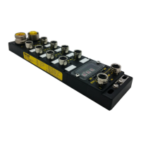
IP67 IO-Link Modules for EtherNet/IP
GIF: Global Input filter
This parameter applies debounce filtering to all digital inputs (DI – Pin2) and prevents the processing of fast
input state changes, like those caused by contact bouncing. Signal changes are ignored according to the filter
time applied and is only registered when the changed polarity has remained fully stable over a given window
time (every new change resets the filter timer).
0: 0ms
1: 1ms
2: 3ms
3: 5ms
IO Mode
This parameter allows configuring the pin2 (channels number C1, C3, C5, C7, C9, C11, C13, C15) and the
pin4 (channels number C0, C2, C4, C6, C8, C10, C12, C14)
For Pin2: For Pin4:
0 = Digital Input (DI) 0 = Standard Input (SI)
1 = Digital Output (DO) 1 = Standard Output (SO)
2 = Extended Power Supply 2 = Standard Input with IO-Link (Refer to chapter SI with IO-Link)
3 = IO-Link
Note!
“Power Supply” on Pin2 is a 24 voltage applied continuously after the EtherNet/IP
connection. It allows to power up the Molex IO-Link hub TEDIO-8D0P-808 and TEDIO-
8B4P-808.
DO / SO Fail-Safe Mode
This parameter is used for setting the fail-safe value behavior of Digital Output (DO) configured on Pin#2 and
of Standard Digital Output (SO) configured on Pin4.
Fail-safe value will be applied in the below conditions:
- When the Scanner is switched from RUN to PROG (IDLE mode)
- In the event of loss of bus communication (Cable disconnected, connectionTime-out, inhibit mode…)
0 = Reset to 0
1 = Hold Output State. When the communication failure occurs, the output remains in the last state
sent by the PLC
Note!
If Pin#2 is defined as Extended Power Supply, the fail-safe mode will be ignored (Fail-
safe value not applied).
Note!
If the IO-Link port is in operate mode while the fail-safe mode is triggered, the IO-Link
device will apply its own fail-safe mode. Invalid data status will be indicated into the
Input assembly.
DI / SI Invert
This parameter changes the polarity of the digital inputs. Therefore, the Input Process Data will also report this
inversion.
It could be used to treat normally close sensors in positive logic.
0 = Normal
1 = Inverted