IP67 IO-Link Modules for EtherNet/IP
Warning!
If you change the rotary position while the EtherNet/IP scanner has an I/O connection
established, the connection will be closed and the Fail Safe Mode will be applied. A
reset command or a power cycle will be required.
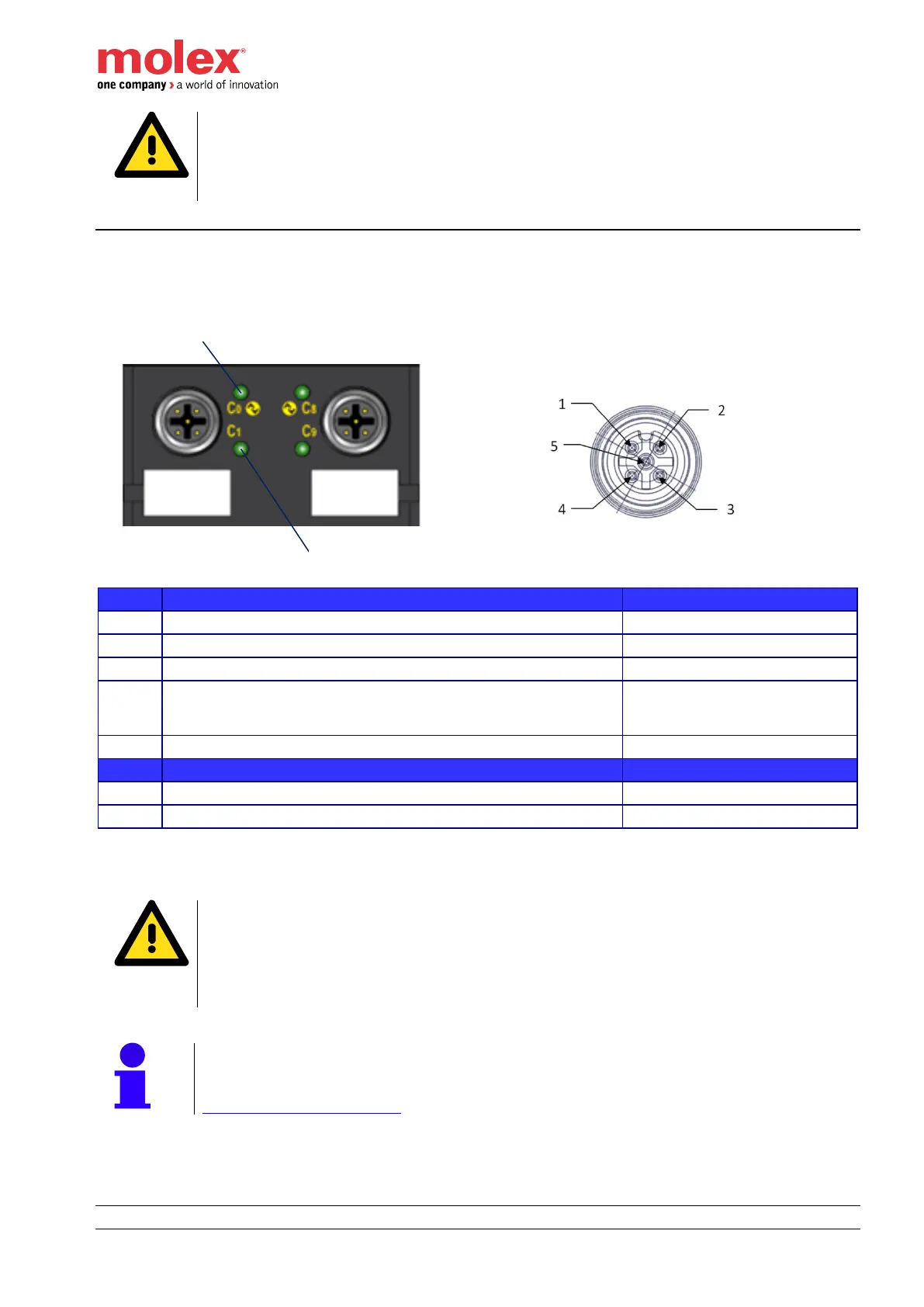
I/O connectors
Pinout and orientation
I/O Connector - Description
D_I/O - Digital Input (DI) or output (DO) - Configurable
C/Q, IO-Link data transmission cable. It can also be configured
as Standard Digital Input (SI), Standard Digital Output (SO) and
as Extended Power Supply (EPS)
Tri-color red/blue/green LED for even channel indicator– Pin4
Bi-color red/green LED for odd channel indicator – Pin2
connection for communication (C) or switching (Q) signal (SIO)
Warning!
When a potential is applied on SIO/IO-Link channel (Pin 4), the difference between the
value of this external potential and the UB shall not be higher than 0.3 V.
A value higher than 0.3 V will result a destruction of the HarshIO module.
An external potential with a value lower than UB is accepted.
Note!
Shell of each I/O Port connector is connected to Functional Earth. Refer to Chapter
Functional earth connections.