IP67 IO-Link Modules for EtherNet/IP
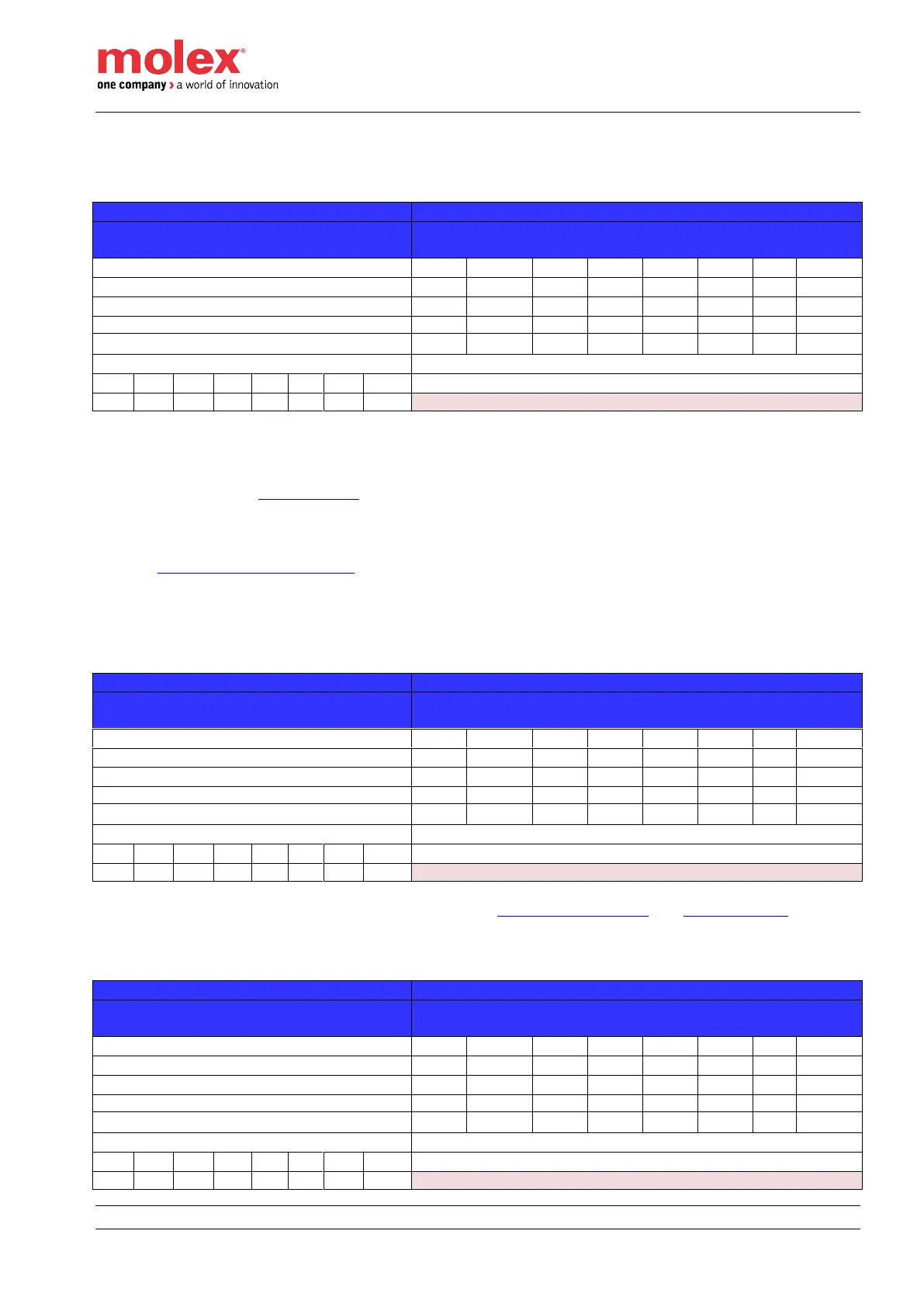
Output process data mapping
Assembly #121 - Digital data + with 4 bytes data per IO-Link device
Output Process Data (4 bytes)
Offset (in byte) per IO-Link channel
IO-Link Process Data (4 bytes)
IO-Link Output Process Data (4bytes)
SOx: SO - Standard Output data (x = Channel number) – Pin4
DOx: DO - Digital Output data (x = Channel number) – Pin2
CSICx: Command to Switch an IO-Link port configured in IO-Link mode to SI mode (x = Channel number –
Pin4). Refer to chapter SI with IO-Link.
• 0 – SI mode
• 1 – IO-Link mode
EFA: Electrical Fault Acknowledgement. This toggle bit is used to manually acknowledge the electrical fault.
Refer to configuration assembly #100 for Electrical Fault Acknowledgement Mode.
IO-Link Input Process Data: Area where the IO-Link process data are mapped.
Assembly #122 - Digital data + with 8 bytes data per IO-Link device
Output Process Data (4 bytes)
Offset (in byte) per IO-Link channel
IO-Link Process Data (8 bytes)
IO-Link Output Process Data (8 bytes)
For Output and IO-Link Process Data information, refer to output assembly #121 and assembly #122
Assembly #123 - Digital data + with 32 bytes data per IO-Link device
Output Process Data (4 bytes)
Offset (in byte) per IO-Link channel
IO-Link Process Data (32 bytes)
IO-Link Output Process Data (32 bytes)