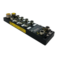
IP67 IO-Link Modules for EtherNet/IP
Note!
M12 accessories (cordsets, plugs …) connected to the module I/O and network
connectors shall be screwed with a torque of 2.0 Nm to ensure a correct sealing to
achieve IP67 rating.
Note!
At the module power up and before the first connection with the PLC, Pin #2 & Pin #4
are configured as Digital Input.
Note!
The IO-Link devices can be connected to the I/O connector via 3, 4 or 5-wire standard
cables with a maximum length of 20 m.
Channel LEDS and status bits
The table below shows the LEDs behavior, the description and the corresponding status bits.
DI:
DO:
SI:
SO:
EPS:
IO-Link:
Digital Input configured on Pin2
Digital Output configured on Pin2
Standard digital Input configured on Pin4
Standard digital Output configured on Pin4
Extended Power Supply
IO-Link configured
Input process data -
Status bit
C1, C9
C3, C11
C5, C13
C7, C15
(Pin 2)
DI configured but not activated (not set to 1)
DO configured but not energized
DI activated.
DO / EPS energized
DO / EPS: when shorted to ground
DO: when overload detected (>500mA)
DO / EPS energized and overvoltage on UB (> 30 V)
DO / EPS energized and overcurrent on UB (>~10A)
DO / EPS energized and under voltage (UB <19.2V)
DO / EPS: when energized and UL is overvoltage (UL > 30 V)
DO / EPS: when energized and UL is under voltage (UL <19.2V)
DI/DO/EPS configured: when L+ is shorted
DI/DO/EPS: when L+ is overloaded (1.6A)
C0, C8
C2, C10
C4, C12
C6, C14
(Pin 4)
SI not activated
SO not energized
IO-link is not activated
Shows the status of the Port in SIO mode:
- SI activated
- SO energized
The BLUE led shows the actual IO-Link communication state
IO-link Device connected and in OPERATE state.