moog
MSD Servo Drive Compact Operation Manual
14
to the glossary
to the table of contents
Id no.: CA97555-001, Rev. 3.0 - Date: 0 6/2012
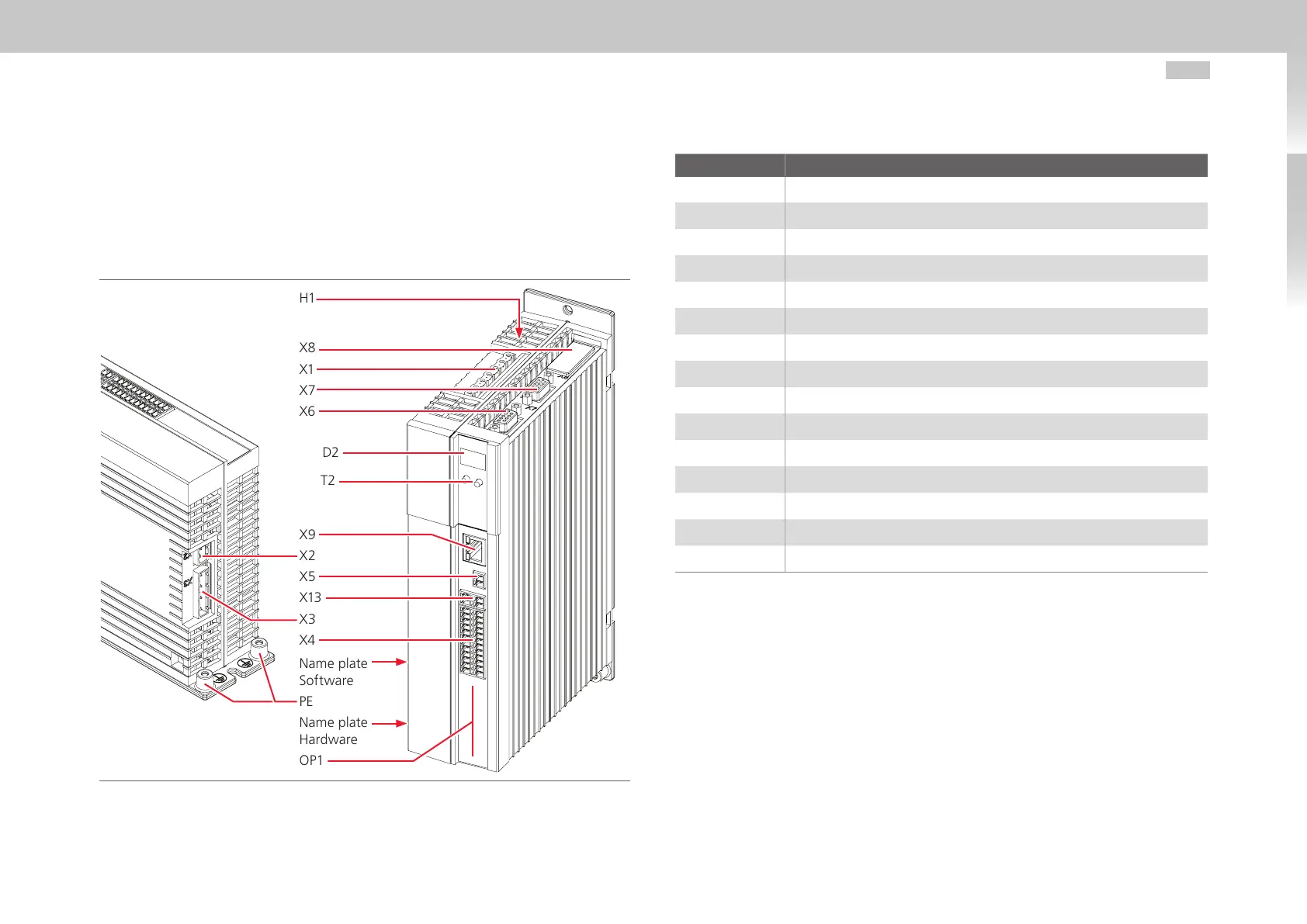
3.2 Layout
The following shows the layout with the corresponding positions of plugs and terminals.
For better orientation we have identified the designations of plugs and terminals with an
abbreviation.
Fig. 3.1 Layout MSDServoDriveCompact
H1
X8
X1
X7
X6
D1, D2
T1, T2
X9
X2
X5
X13
X3
X4
Name plate
Software
PE
Name plate
Hardware
OP1
Number Designation
D1, D2 7-segment display
H1 DC link voltage indicator LED
OP1 Installation space for option 1 (Communication)
PE Connection PE conductor
T1, T2 Button
X1 Power connection
X2 Connection control supply U
V
X3 Connection AC power supply
X4 Terminals
X5 Motor temperature monitoring
X6 Connection resolver
X7 Connection high-resolution encoder
X8 Option 2 (Technology)
X9 Ethernet interface
X13 Connection Motor brake
Table 3.1 Key to layout MSDServoDriveCompact