moog
MSD Servo Drive Compact Operation Manual
38
to the glossaryto the table of contents
Id no.: CA97555-001, Rev. 3.0 - Date: 0 6/2012
4.3 Serial commissioning
An existing parameter dataset can be transferred to other MSDServoDriveCompacts by
using Moog
DriveADministr Ator 5. Details can be found in the
Moog D
riveA DministrAtor 5 help system.
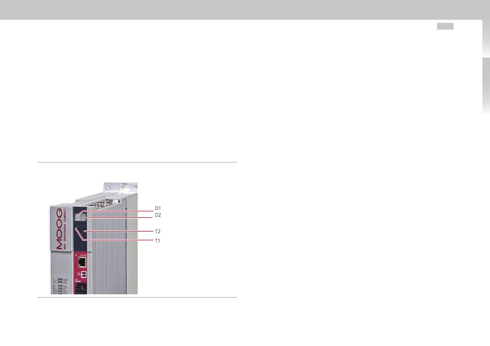
4.4 Integrated control unit
The built-in operator control unit permits diagnostics of the MSDServoDriveCompact.
The operator control unit comprises the following elements, all located on the front of
the device:
• 2-digit 7-segment display (D1, D2)
• 2 buttons (T1, T2)
Fig. 4.1 Integrated control unit MSDServoDriveCompact
The following functions and displays are available:
• Display of device state (see section 5.1 "Device states“ on page 43)
The device state is displayed after switching on the control voltage. If no input is
made via the keypad for 60seconds, the display switches back to the device state.
• Display of device error state (see page 43)
If a device error occurs the display immediately switches to show the error code.
• Parameter setting (display "PA") (see section 4.4.3)
Resetting device parameters to their factory setting.
• Ethernet IP address setting (display "IP") (see section 4.4.4)
Setting of the Ethernet IP address and the subnet mask.
• Fieldbus settings (display "Fb") (see section 4.4.5)
Setting of fieldbus address for example.
D1
D2
T2
T1