moog
MSD Servo Drive Compact Operation Manual
15
[ Installation ]
to the glossaryto the table of contents
Id no.: CA97555-001, Rev. 3.0 - Date: 0 6/2012
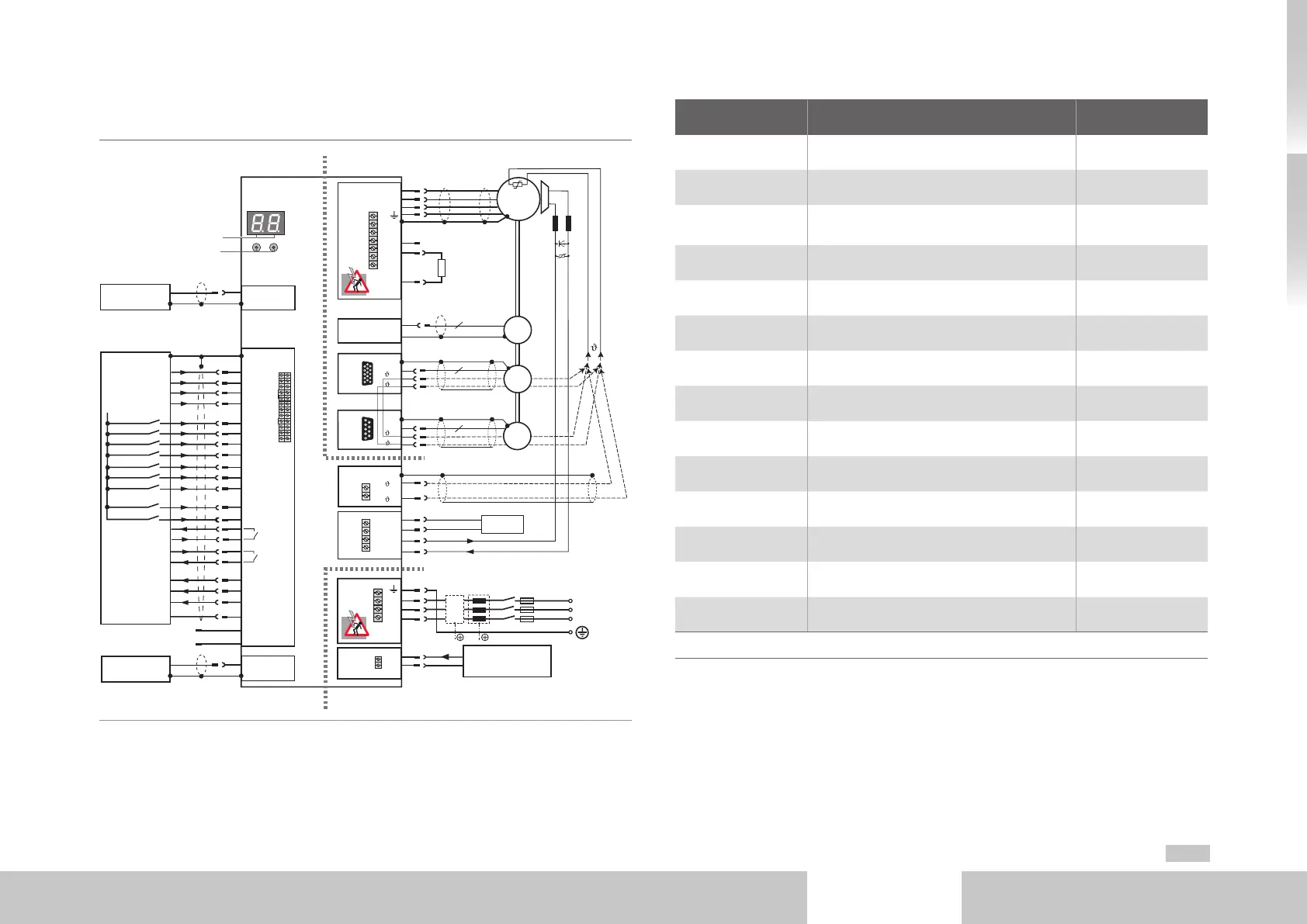
3.3 Connection diagram
Ethernet
ISD00
ISD01
ISD02
OSD02
Relay
ENPO (STO)
Motor
3
Option 2
Control
Service
interface
ISDSH (STO)
ISA00+
ISA00-
ISA01+
ISA01-
Analog setpoint 1
Analog setpoint 2
+24 V DC against
I/O-GND
+24 V (U
H
)
3
4
5
6
10
15
16
17
9
23
24
22
RSH
Diagnosis
STO
12
11
1
2,14
13
I/O-GND
Relay
Digital2
RB
L+
L-
Braking
resistor
U
V
W
6
n
n
ISD03
ISD04
ISD05
18
19
20
ISD0621
OSD01
8
Digital1
OSD00
7
Digital0
GND
GND
V+
OSD03
2
3
4
1
5
9
10
9
DC link
OSD04
54321
10 9876
15 14 13 12 11
DGND
DGND
43 21
9876
~
1+
1-
1+
1-
+
-
(-)(+)
D1, D2
T1, T2
L1
K1
L2
L3
FN
L1
L2
L3
3-phase system
X3
X2
X9
X4
X8
X7
X6
X5
X13
X1
Front
Option 1
+24 V DC supply for
control electronics (U
V
)
Communication
Fieldbuses
Brake (+)
+24 V DC supply
for brake
Brake (-)
Resolver
-
+
Encoder
+
–
TOP
BOTTOM
Fig. 3.2 Connection diagram
Number Designation Details
D1, D2 7-segment display page39
T1, T2 Button page39
X1
Connection for motor, braking resistor and
measurement of DC link voltage
page30
X2 Connection control supply page21
X3 Connection AC power supply page21
X4 Terminals page24
X5 Connection motor temperature monitoring
1)
page30
X6 Connection resolver
1)
page28
X7 Connection high-resolution encoder
1)
page29
Option 1 Communication page26
PE Connection PE conductor page19
X8 (Option 2) Technology page26
X9 Ethernet interface page26
X13 Connection motor brake
page30
1) NOTE: The temperature sensor of the motor winding can be optionally connected via the encoder cables (X6 or X7) or to
terminal X5.
Table 3.2 Key to connection diagram