moog
MSD Servo Drive Compact Operation Manual
20
to the glossary
to the table of contents
Id no.: CA97555-001, Rev. 3.0 - Date: 0 6/2012
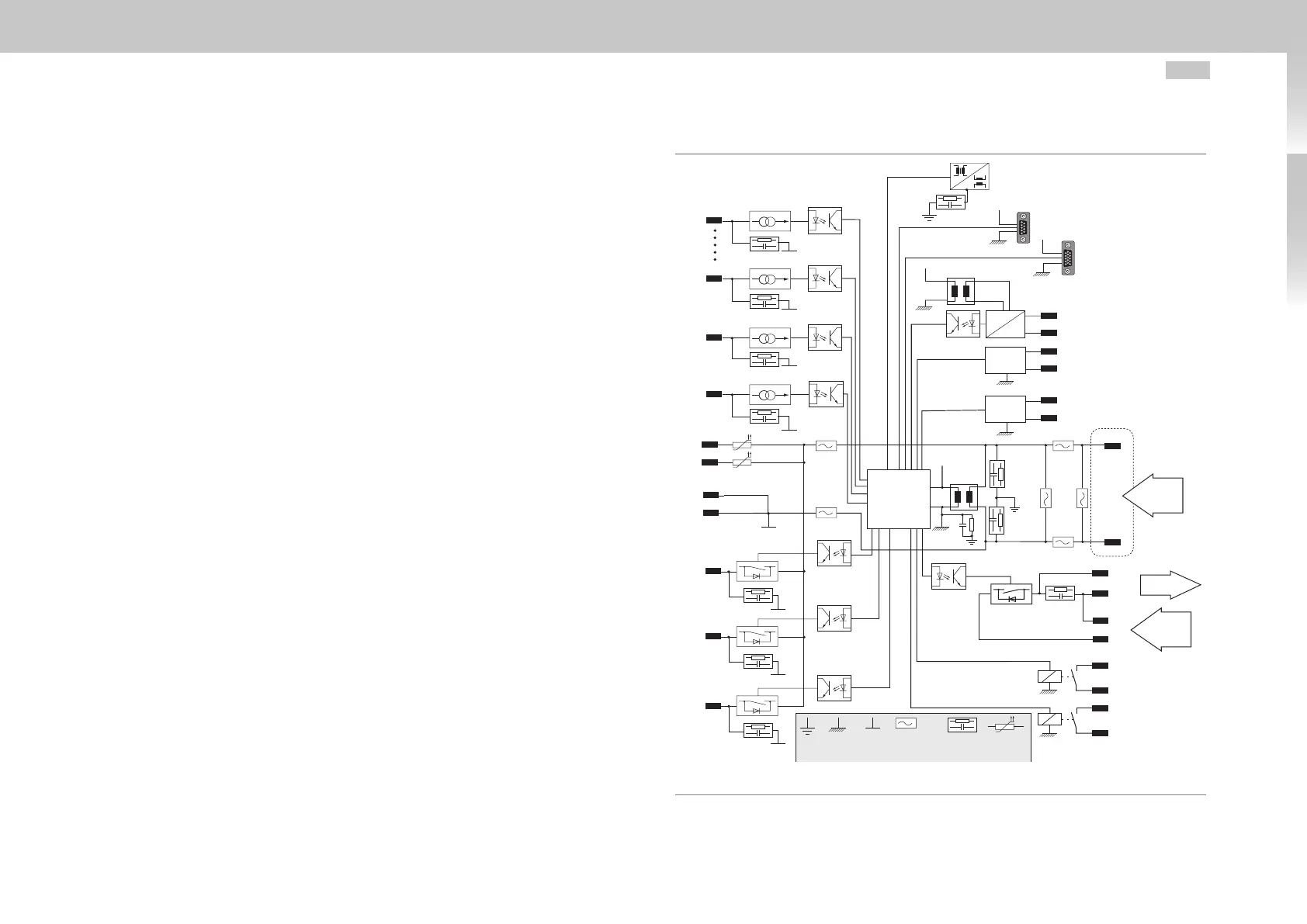
3.6 Electrical isolation concept
The control electronics, with its logic (µP), the encoder terminals and the inputs and
outputs, are electrically isolated from the power section (power supply/DC link). All
control terminals are designed as safety extra-low voltage/protective extra-low voltage
(SELV/PELV) circuits and must only be operated with such SELV/PELV voltages, as per
the relevant specification. This provides reliable protection against electric shock on the
control side.
A separate control supply, compliant with the requirements of a SELV/PELV, is therefore
needed.
The opposite overview shows the potential supplies for the individual terminals in detail.
This concept also delivers higher operational safety and reliability of the drive.
SELV = Safety Extra Low Voltage
PELV = Protective Extra Low Voltage
PE GNDµP
DGND
complexe
not linear
impedance
RC link Polyswitch
GNDµP
GNDµP
GNDµP
X4/15
ISD00
ISD01
I
LIM
X4/21
ISD06
I
LIM
X4/10
ENPO
I
LIM
X4/22
ISDSH
I
LIM
X4/7
OSD00
X4/3
ISA00+
Motor PTC
X4/4
ISA00-
ISD02
ISD03
ISD04
ISD05
A/D
A/D
ISA01+
X4/5
X4/6
ISA01-
X4/14
GNDµP
GNDµP
GNDµP
GNDµP
GNDµP
DGND
DGND
DGND
DGND
DGND
DGND
DGND
DGND
X4/2
ϑ
F1
ϑ
F2
X4/13
DGND
X4/1
ϑ
F3
V
µP
V
µP
V
µP
V
µP
µP
X4/8
OSD01
OSD03
Motor brake
GND
X4/9
OSD02
X5/
ϑ+
X5/
ϑ−
RSH
X13/2
X13/1
X4/12
X4/11
OSD04
X4/23
X4/24
Ethernet
X9
Resolver
X6
Encoder
X7
PE
U
V
U
V
X2/+
X2/-
U
H
24 V DC
control
supply
24 V DC
Supply
brake
GND
X13/3
X13/4
Fig. 3.9 Electrical isolation concept MSDServoDriveCompact