moog
MSD Servo Drive Compact Operation Manual
24
to the glossary
to the table of contents
Id no.: CA97555-001, Rev. 3.0 - Date: 0 6/2012
3.8 Control connections
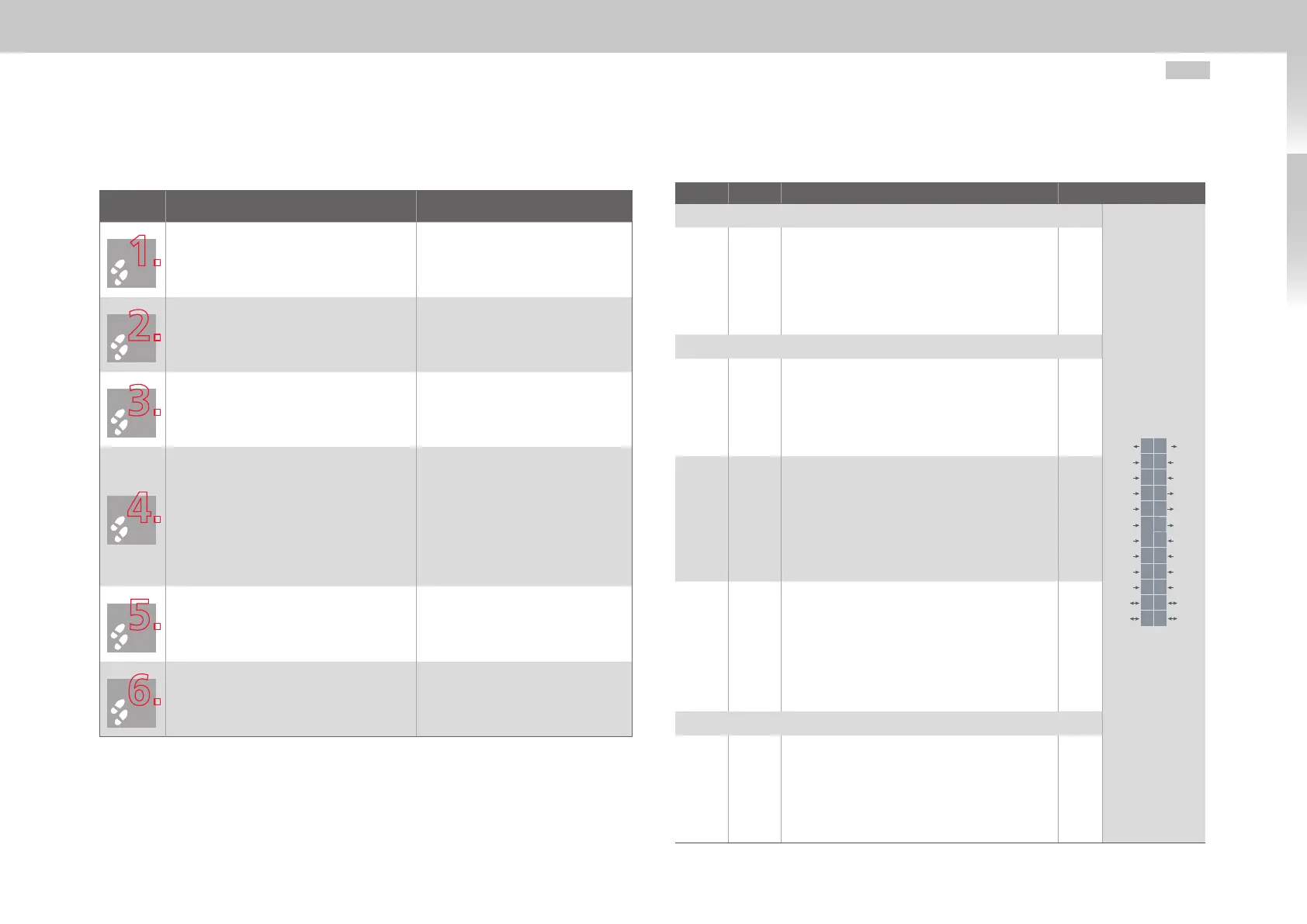
Step Action Comment
Check whether a complete device setup is
already available, i.e. whether the drive has
already been configured.
If this is the case, a special control terminal
assignment applies.
Please contact your project engineer to
obtain the connecting assignment!
Choose a connecting assignment. Initial commissioning
Wire the control terminals with shielded
cables.
The following is strictly required: STO
request X4/22, ENPO X4/10 and a start
signal (with control via terminal).
Ground the cable shields over a wide
area at both ends.
Conductor sizes fixed: 0.2 to 1.5mm²
Flexible conductor sizes:
- Ferrule without plastic sleeve:
0.2 to 1.5mm²
- Ferrule with plastic sleeve:
0.2 to 0.75mm²
Keep all contacts open
(inputs inactive).
Check all connections again!
Continue with commissioning in
section 4.
Note the following points:
• Always wire the control terminals with shielded cables.
• Lay the control cables separately from the mains power and motor cables.
• A cable type with double copper braiding, with 60 - 70% coverage, must be used
for all shielded connections.
3.8.1 Specification of control connections
Des. Term. Specification El. isolation
Analog inputs
REL
REL
ISDSH
ISD06
ISD05
ISD04
ISD03
ISD02
ISD01
ISD00
+24V
DGND
RSH
RSH
ENPO
OSD02
OSD01
OSD00
ISA1-
ISA1+
ISA0-
ISA0+
+24V
DGND
24
23
22
21
20
19
18
17
16
15
14
13
12
11
10
9
8
7
6
5
4
3
2
1
ISA0+
ISA0-
ISA1+
ISA1-
X4/3
X4/4
X4/5
X4/6
• U
IN
= ±10VDC
• Resolution 12Bit; R
IN
approx.101kΩ
• Terminal scan cycle in "IP mode" = 125µs,
otherwise = 1ms
• Tolerance: U±1% of the measuring range
end value
no
Digital inputs
ISD00
ISD01
ISD02
ISD03
ISD04
X4/15
X4/16
X4/17
X4/18
X4/19
• Frequency range <500Hz
• Terminal scan cycle in = 1ms
• Switching level Low/High: ≤4.8V / ≥18V
• U
IN max
= +24VDC +20%
• I
IN
at +24VDC = typ. 3mA
yes
ISD05
ISD06
X4/20
X4/21
• Frequency range ≤500kHz
• Switching level Low/High: ≤4.8V / ≥18V
• U
IN max
= +24VDC +20%
• I
IN max
at +24VDC = 10mA, R
IN
approx. 3kΩ
• internal signal delay time < 2 s suitable
as trigger input for quick saving of actual
position
yes
ENPO X4/10
• Disable restart inhibit (STO) and enable power
stage = High level
• OSSD-capable
• Reaction time approx. 10ms
• Switching level Low/High: ≤4.8V / ≥18V
• U
IN max
= +24VDC +20%
• I
IN
at +24VDC = typ. 3mA
yes
Digital outputs
OSD00
OSD01
OSD02
X4/7
X4/8
X4/9
• No destruction in case of short-circuit
(+24VDC -> DGND), but device may briefly
shut down.
• I
max
= 50mA, PLC-compatible
• Terminal scan cycle in = 1ms
• High-side driver
yes
Table 3.5 Specification of control connections X4