moog
MSD Servo Drive Compact Operation Manual
31
[ Installation ]
to the glossaryto the table of contents
Id no.: CA97555-001, Rev. 3.0 - Date: 0 6/2012
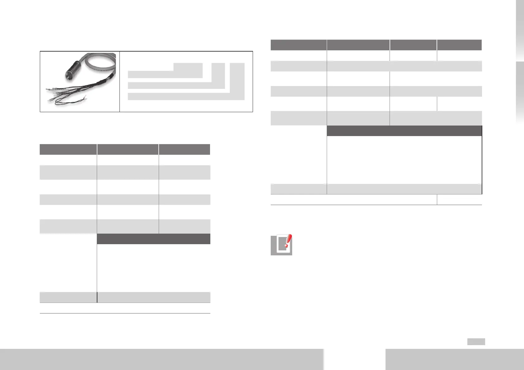
3.13.2 Ready made-up motor cable
C08336 - xxx yyy
1)
Ready made-up motor cable
Configuration option
Cable length (m)
1) yyy stands for length in meters; standard length: 1 m, 5 m, 10 m, 15 m, 20 m, 50 m. Further length on request
Motor cable C08336-xxx-yyy Order code
Technical data motor cable
Technical data C08336-xxx-yyy
1),2)
CB05708-xxx-yyy
1),2)
Continous rated current 10A TBD
Surge current
30A (90s at +72.7°C)
(+162.9°F)
TBD
Minimum bend radius
In fixed installation: 60mm
In flexible use: 120mm
TBD
Cable diameter range 9 to 14.4mm TBD
Cable cross-section
4 x 1.5mm² +
2 x 1mm²
4 x 4mm² +
2 x 1.5mm²
Temperature range
-50°C to +90°C
(-58°F to +194°F)
TBD
Wiring
Connector pin / Wiring
2 / U
4 / VV
1 / WWW
PE / yellow; green
5 / Brake +; white
6 / Brake -; black
Connector housing / Screen
Connector type Size 1
2)
xxx-001 for standard configuration option, others on request
Table 3.13 Technical data motor cable (Connector type Size1)
Technical data C08733-xxx-yyy
1),2)
B47916-xxx-yyy
1),2)
CA98676-yyy
1),2)
Continous rated current 44A 61A 82A
Surge current TBD
Minimum bend radius
In fixed installation: 60mm
In flexible use: 120mm
TBD
Cable diameter range 16.2 ±3mm TBD
Cable cross-section
4 x 6mm² +
2 x 1mm²
4 x 10mm² +
2 x 1.5mm²
4 x 16mm² +
2 x 1.5mm²
Temperature range
-50°C to +90°C
(-58°F to +194°F)
TBD
Wiring
Connector pin / Wiring
U / U
V / VV
W / WWW
PE / yellow; green
+ / Brake +; white
- / Brake -; black
Connector housing / Screen
Connector type Size 1.5
2)
xxx-001 for standard configuration option, others on request
Table 3.14 Technical data motor cable (Connector type Size1.5)
NOTE: Wires 5 and 6 (PTC) are required only for motors in which the motor
PTC cannot be connected via the encoder cable. In the case of synchronous
motors with resolver, the PTC is connected via the resolver cable.