moog
MSD Servo Drive Compact Operation Manual
25
[ Installation ]
to the glossaryto the table of contents
Id no.: CA97555-001, Rev. 3.0 - Date: 0 6/2012
Des. Term. Specification El. isolation
STO "Safe Torque Off"
REL
REL
ISDSH
ISD06
ISD05
ISD04
ISD03
ISD02
ISD01
ISD00
+24V
DGND
RSH
RSH
ENPO
OSD02
OSD01
OSD00
ISA1-
ISA1+
ISA0-
ISA0+
+24V
DGND
24
23
22
21
20
19
18
17
16
15
14
13
12
11
10
9
8
7
6
5
4
3
2
1
ISDSH
(STO)
X4/22
• "Request STO" input = Low level
• OSSD-capable
• Switching level Low/High: ≤4.8V / ≥18V
• U
IN max
= +24VDC +20%
• I
IN
at +24VDC = typ. 3mA
yes
RSH
RSH
X4/11
X4/12
Diagnostics STO, both tripping
channels active, one NO contact
with automatically resetting circuit-
breaker (polyswitch)
• 25V / 200mAAC, cosϕ = 1
• 30V / 200mADC, cosϕ = 1
X4/12
X4/11
yes
Relay outputs
REL
X4/23
X4/24
Relay, 1 NO contact
• 25V / 1.0AAC, cosϕ = 1 (AC1)
• 30V / 1.0ADC, cosϕ = 1 (DC1)
• Switching delay approx. 10ms
• Cycle time 1 ms
X4/24
Auxilliary voltage
+24V
X4/2
X4/14
• Auxiliary voltage output (U
H
) to feed the
digital control inputs
• U
H
= U
V
-∆U (∆U typically approx. 1.2V),no
destruction in case of short circuit (+24VDC
-> DGND), but device may briefly shut down.
• I
max
= 80mA (per pin) with self-resetting
circuit breaker (polyswitch)
yes
Digital ground
DGND
X4/1
X4/13
Reference ground for +24VDC yes
Table 3.5 Specification of control connections X4
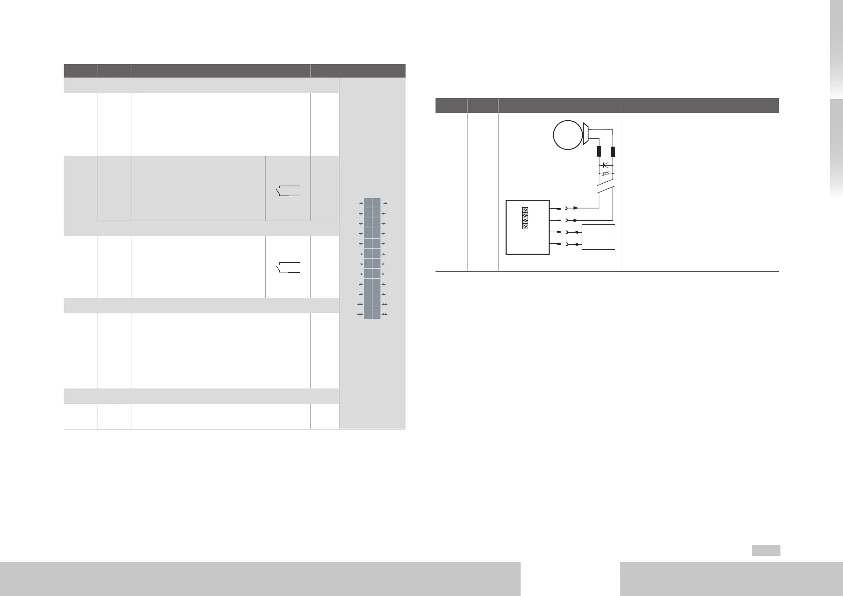
3.8.2 Connection of motor brake X13
Connector X13 (C2 to C4) is intended for connection of a motor brake.
Des. Term. Connection Specification
OSD03
GND
GND
V+
X13/2
X13/1
X13/3
X13/4
Motor
3
GND
OSD03
1
2
~
X13
Front
Brake (+)
Brake (-)
V+
GND
3
4
24 V DC
supply for
brake
• Short-circuit proof
• External control supply +24VDC
(I
IN
= 2.1 A) required via X13/3 (GND)
and X13/4 (V+)
• U
BR
= U
V
-∆U` (∆U` typically approx.
1.4V)
• To actuate a motor holding brake up to
I
BR
= 2.0 A maximum (for brakes with
higher current requirements a relay
must be interposed).
• Overcurrent causes cyclic shutdown
• Also usable as configurable digital
output
• Interruptible cable break monitor
< 200mA typically in condition "1"
Table 3.6 Specification of the terminal connections X13