moog
MSD Servo Drive Compact Operation Manual
30
to the glossary
to the table of contents
Id no.: CA97555-001, Rev. 3.0 - Date: 0 6/2012
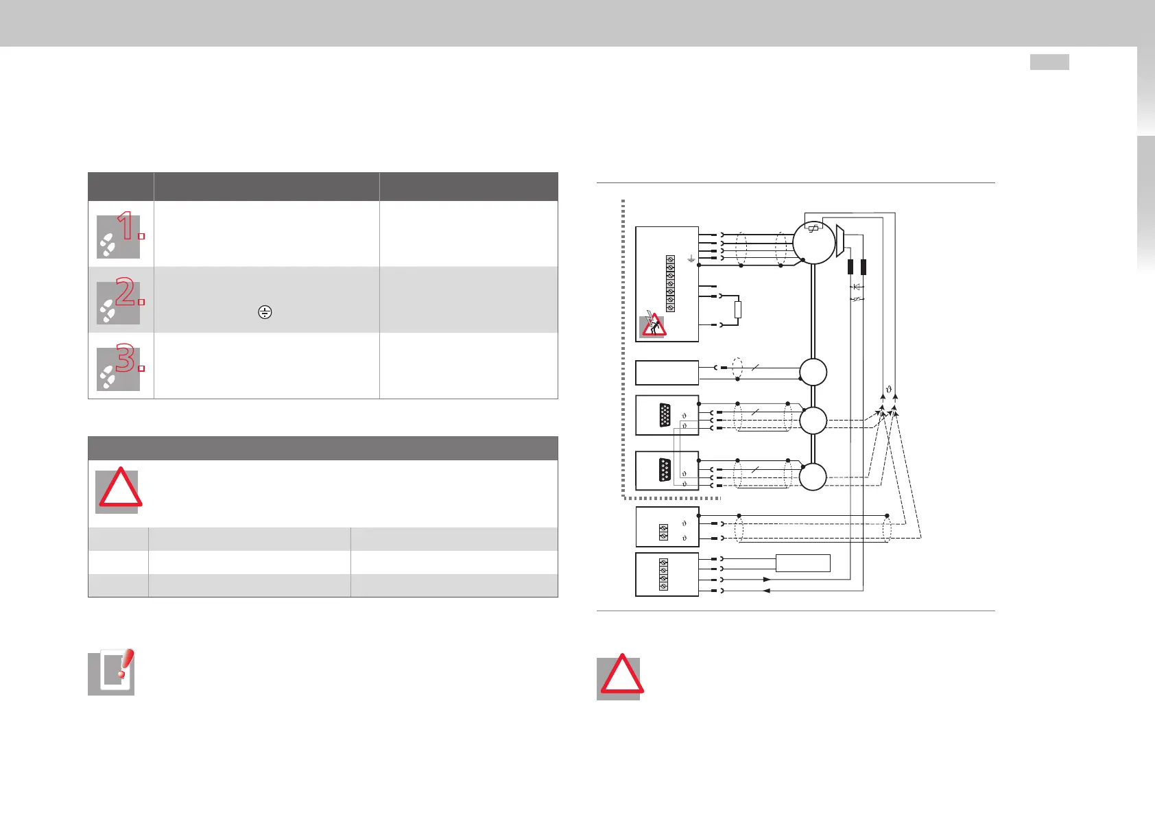
3.13 Motor connection
Step Action Comment
Specify the cable cross-section dependent
on the maximum current and ambient
temperature.
Cable cross-section according
to local and country-specific
regulations and conditions.
Connect the shielded motor cable to
terminals X1/ U, V, W and connect the
motor to ground at .
Mount shield at both ends to
reduce interference emission.
Wire the motor temperature sensor and
activate temperature evaluation by means
of Moog Dri veADministrAtor. See also
related note.
Mount shield at both ends to
reduce interference emission.
Motor temperature sensor
ATTENTION! The motor PTC when connected to X5 must be provided with
basic insulation, against the motor winding and when connected to X6
or X7 must be provided with reinforced insulation as per
EN61800-5-1.
X5 Temperature switch (Klixon), PTC Sensor with basic insulation
X6 Temperature switch (Klixon), PTC, KTY Sensor with increased insulation
X7 Temperature switch (Klixon), PTC, KTY Sensor with increased insulation
Table 3.12 Motor temperature sensor terminal configuration
NOTE: In the event of a short-circuit or ground fault in the motor cable, the
power stage is disabled and an error message is issued.
!
3.13.1 Connection of the servo motors
Please use a ready made-up motor cable to connect servo motors.
Motor
3
Option 2
RB
L+
L-
Braking
resistor
U
V
W
6
n
n
5
9
10
9
DC link
~
1+
1-
1+
1-
+
-
(-)(+)
X8
X7
X6
X5
X13
X1
Front
Brake (+ )
Brake (-)
Resolver
Encoder
Top
GND
GND
V+
OSD03
2
3
4
1
24 V DC supply
for brake
Fig. 3.16 Connection of motor
ATTENTION! DC linking of multiple servo drives is not permitted!
!