moog
MSD Servo Drive Compact Operation Manual
22
to the glossary
to the table of contents
Id no.: CA97555-001, Rev. 3.0 - Date: 0 6/2012
C2 and C3
+
X2
X3
L1
L2
L3
L1
N
Mains
filter
Mains
choke
1-phase
system
K1F1
Fig. 3.12 Conection C2 and C3 mains supply 1x230V
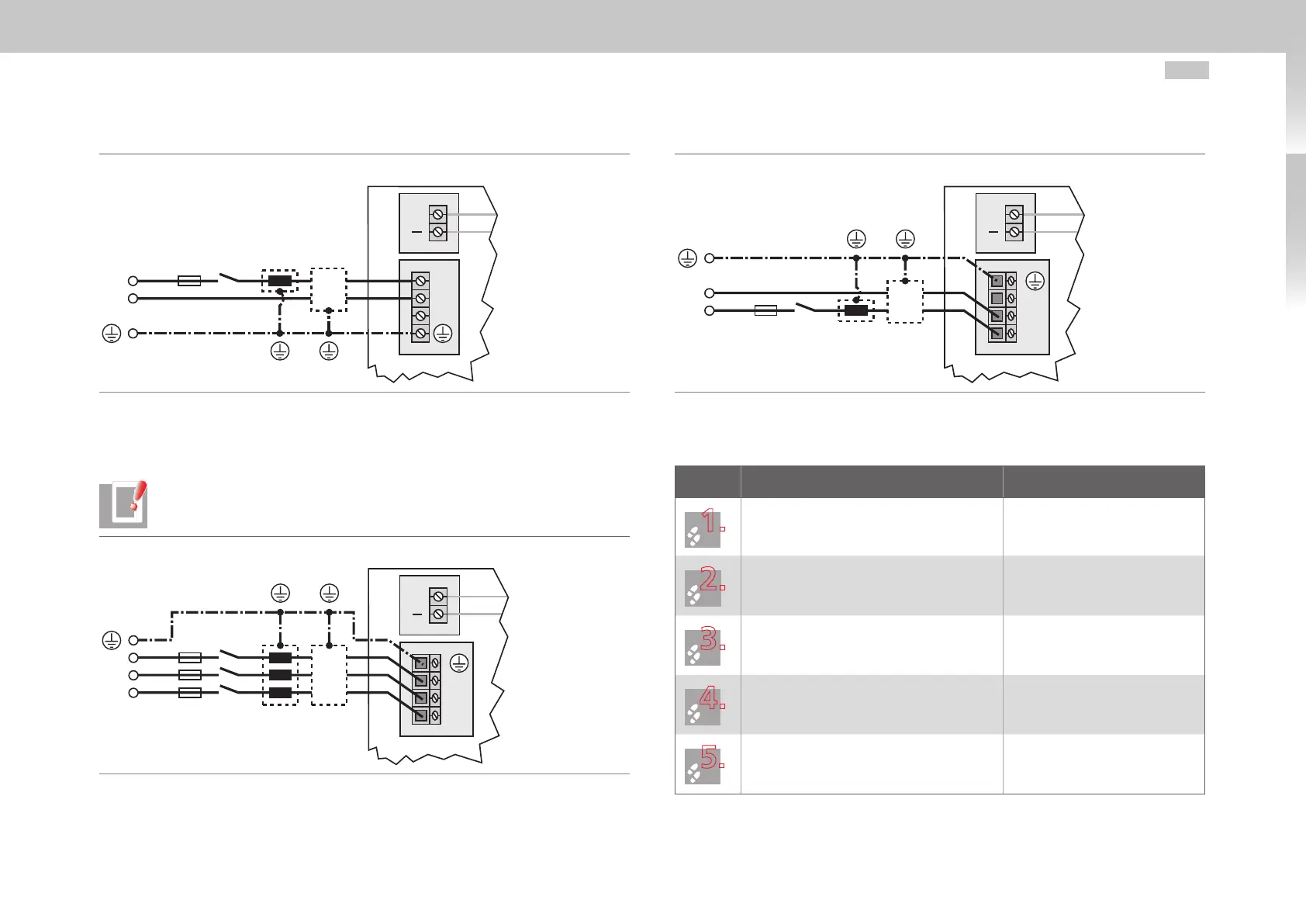
3.7.3 Connection of mains supply C4
NOTE: Before commissioning, the value of the connected mains voltage must
be set on the drive (factory setting = 3x230VAC / 3x400VAC).
C4
+
X2
X3
L1
L2
L3
L1
L2
L3
Mains
filter
Mains
choke
3-phase
system
K1F1
Fig. 3.13 Connection C4 mains supply 3x230V (G394-080) or 3x400V (G394-065) depending
on device design
C4
+
X2
X3
L1
L2
L3
L1
N
Mains
filter
Mains
choke
1-phase
system
K1F1
Fig. 3.14 Connection C4 mains supply 1x230V
Procedure:
Step Action Comment
Specify the cable cross-section dependent
on the maximum current and ambient
temperature.
Cable cross-section according to
local regulations and conditions.
Wire the drive with the mains filter
*)
,
maximum cable length 0.3 m (with non-
shielded cable)!
Wire the mains choke
*)
(if installed)
Reduces the voltage distortions
(THD) in the system and prolongs
the life of the drive.
Install a K1 circuit breaker (power circuit
breaker, contactor, etc.).
Do not switch on the power!
Use mains fuses (duty class gG) to isolate all
poles of the drive from the mains supply.
For compliance with equipment
safety requirements laid down in
EN61800-5-1
*)
optional