moog
MSD Servo Drive Compact Operation Manual
37
[ Commissioning ]
to the glossaryto the table of contents
Id no.: CA97555-001, Rev. 3.0 - Date: 0 6/2012
− Certain motors are intended for operation on the servo drive.
Direct connection to the mains supply can destroy the motor.
− The motor surfaces may become extremely hot. No temperature sensitive
parts may touch or be mounted to these areas, appropriate measures to
prevent contact must be applied wherever necessary.
− In order to avoid overheating of the motor, the temperature sensor
installed in the winding must be connected to the terminals of the tem-
perature monitoring system for the servo drive (X5 or X6).
− The motor brake (if installed) should be checked for fault-free functioning
before commissioning of the motor. Standstill holding brakes are only
designed for a limited number of emergency braking operations. se as
working brake is strictly prohibited.
Display reading after switching on the AC mains supply
D1 D2 Action Reaction Explanation
Switching on the
AC mains supply
Control ready,
power stage ready,
control deactivated
Device is ready for
switching on
Table 4.2 Display D1/D2 after switching on the AC mains supply
NOTES:
• Inputs "ISDSH" and "ENPO"
For step1 in table4.3 at least the two inputs “ISDSH” and “ENPO” for
terminal X4 must be interconnected.
• Manual operation dialog
For step2 in table 4.3 best via the “Manual operation” dialog of
Moog
DriveADministr Ator 5, details can be found in the help system.
• Configuration of inputs/outputs
If step 2 is to be executed via the inputs of terminal X4, the sources for
“START CONTROL” and speed setpoint must be configured accordingly in
the subject area “Inputs/Outputs” of Moog
DriveADministr Ator5.
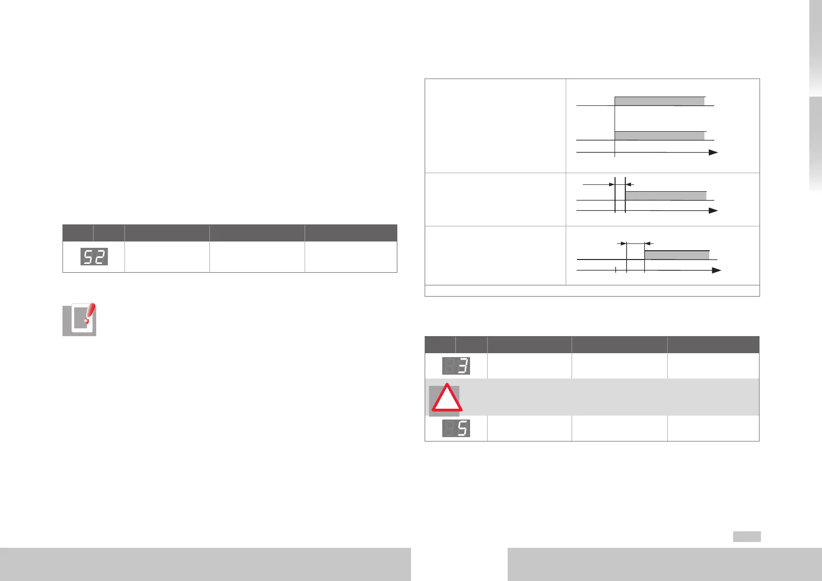
Switching on sequence to start the drive
1. Deactivate the safety function
"STO" by setting the inputs ISDSH”
and “ENPO” (see chapter6).
ISDSH (STO)
ENPO (STO)
1
0
t
1
0
0
2. Activate “START CONTROL” at
the earliest 2 ms after step 1 and
specify the speed setpoint.
START
t
0
1
0
3. Monitor your system or plant and
check the drive behaviour.
TECHNOLOGY ENABLED
(state 5)
t
0
1
0
t = motor dependent delay time
Table 4.3 Switching on sequence
Display reading after start of drive
D1 D2 Action Reaction Explanation
Enable “STO“ and
power stage “ENPO“
Ready for switching on Power stage ready
ATTENTION! Before the next step “Enable start” you must specify a plausible
setpoint, because the pre-set setpoint is transferred to the drive directly after
the motor control has started.
“Start“ enabled Technology enabled
Motor energized,
control active
Table 4.4 Display D1/D2 during activation of motor
Details for optimizing the drive on your application can be found in the
Moog
DriveADministr Ator 5 Online help and in the MSDServoDrive Application Manual.
!