moog
MSD Servo Drive Compact Operation Manual
33
[ Installation ]
to the glossaryto the table of contents
Id no.: CA97555-001, Rev. 3.0 - Date: 0 6/2012
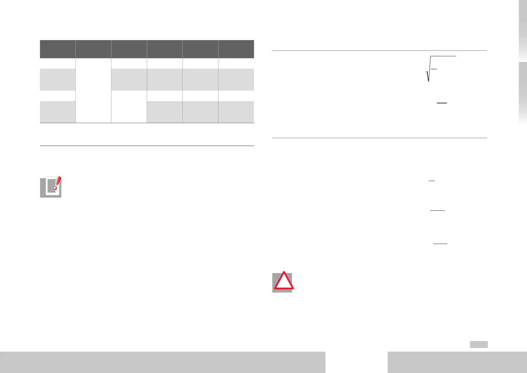
Device Technology
Rated
resistance R
BR
Peak braking
power P
PBr
Pulse
energy W
IBr
K1
G394-059
Wire
resistance
100Ω 1500W 1) 150Ws 120
G394-035 420Ω
1000W
2)
1300W 3)
1400W 4)
140Ws 50
G394-080
90Ω
1690W
1) 6000Ws 170
G394-065
4700W
2)
6170W 3)
6500W 4)
6000Ws 120
1) Data referred to 1 x 230VAC mains voltage (BR switch-on threshold 390VDC)
2) Data referred to 3 x 400VAC mains voltage (BR switch-on threshold 650VDC)
3) Data referred to 3 x 460VAC mains voltage (BR switch-on threshold 745VDC)
4) Data referred to 3 x 480VAC mains voltage (BR switch-on threshold 765VDC)
Table 3.15 Data of the integrated braking resistor (design G394-xxx-xxx-xx2)
If the drive is not permanently operated at its power limit, the saved power dissipation of
the drive can be used as braking power.
NOTE: Further calculation assumes that the drive is used at maximum
permissible ambient temperature. This means that any additional energy input
from the internal braking resistor caused by low ambient temperature will be
neglected.
Method to calculate the continuous braking power:
• Calculation of effective drive loading in a
cycle T:
dti
T
I
T
eff
∫
=
0
2
1
11 K
I
I
P
N
eff
DBr
×−=
Br
T
PBrDBr
dtP
T
P
∫
×≥
0
1
∫
×
=
T
Br
DBr
PBr
dt
P
P
T
0
T
P
P
T
DBr
PBr
BrSum
×=
• Determination of permissible continuous
braking power based on unused drive
power:
11 K
I
I
P
N
eff
DBr
×−=
=
T
Br
DBr
PBr
dt
P
P
T
0
T
P
P
T
DBr
PBr
BrSum
×=
Marginal conditions
• A single braking action must not exceed
the maximum pulse energy of the braking
resistor.
W
IBr
≥ P
PBr
x T
Br
• The continuous braking power calculated
for the device must be greater than the ef-
fective braking power of a device cycle.
dti
T
I
T
eff
∫
=
0
2
1
11 K
I
I
P
N
eff
DBr
×−=
Br
T
PBrDBr
dtP
T
P
∫
×≥
0
1
∫
×
=
T
Br
DBr
PBr
dt
P
P
T
0
T
P
P
T
DBr
PBr
BrSum
×=
This results in the minimum permissible
cycle time T with calculated continuous
braking power:
dti
T
I
T
eff
∫
=
0
2
1
11 K
I
I
P
N
eff
DBr
×−=
Br
T
PBrDBr
dtP
T
P
∫
×≥
0
1
∫
×
=
Br
DBr
PBr
dt
P
P
T
0
The maximum total on-time of the braking
resistor over a specified cycle time T with
calculated continuous braking power results
as:
dti
T
I
T
eff
∫
=
0
2
1
11 K
I
I
P
N
eff
DBr
×−=
Br
T
PBrDBr
dtP
T
P
∫
×≥
0
1
∫
×
=
T
Br
DBr
PBr
dt
P
P
T
0
T
P
P
T
DBr
PBr
BrSum
×=
ATTENTION! No additional external braking resistor may be connected to
drives G394-035 - G394-080 with integrated braking resistor.
!