THEORY OF OPERATION
Spot Welding Manual for Medar 3-4 MOTOMAN
3.3.4 Secondary Resistance
Secondary resistance is the resistance of the entire welding secondary circuitry.
Secondary resistance significantly impacts the amount of I (current) available. In
the following example, the turns ratio is 48:1, and the secondary resistance is 500
micro-ohms.
3.3.5 Reactance, Resistance, and Power Factor
Resistance plays a vital role in the amount of current a welding power source can
deliver. In addition, reactance ((inductance and capacitance), impedance, and
power factor all help determine the capabilities of a welding tool.
An AC current passing through a coil (such as a transformer) is impeded by a
property called inductance. As power passes through the transformer windings,
the current is “stored” in space around the coil in the form of a magnetic field,
while voltage is unimpeded. When the voltage changes direction, this field
collapses, inducing current into the coil once again. Thus, in a phase shift due to
inductance, voltage leads current. The mathematical symbol for inductance is “L.”
Pure resistance applies to both AC and DC currents, but inductance and
capacitance cause an extra type of resistance to AC called impedance. Impedance
is the result of the phase shift that occurs in inductance and capacitance. The
mathematical symbol for impedance is “Z.” If you know inductance (L),
capacitance (C), and resistance (R), you can figure out impedance (Z). The formula
is Z = square root of (L-C)
2
+ R
2
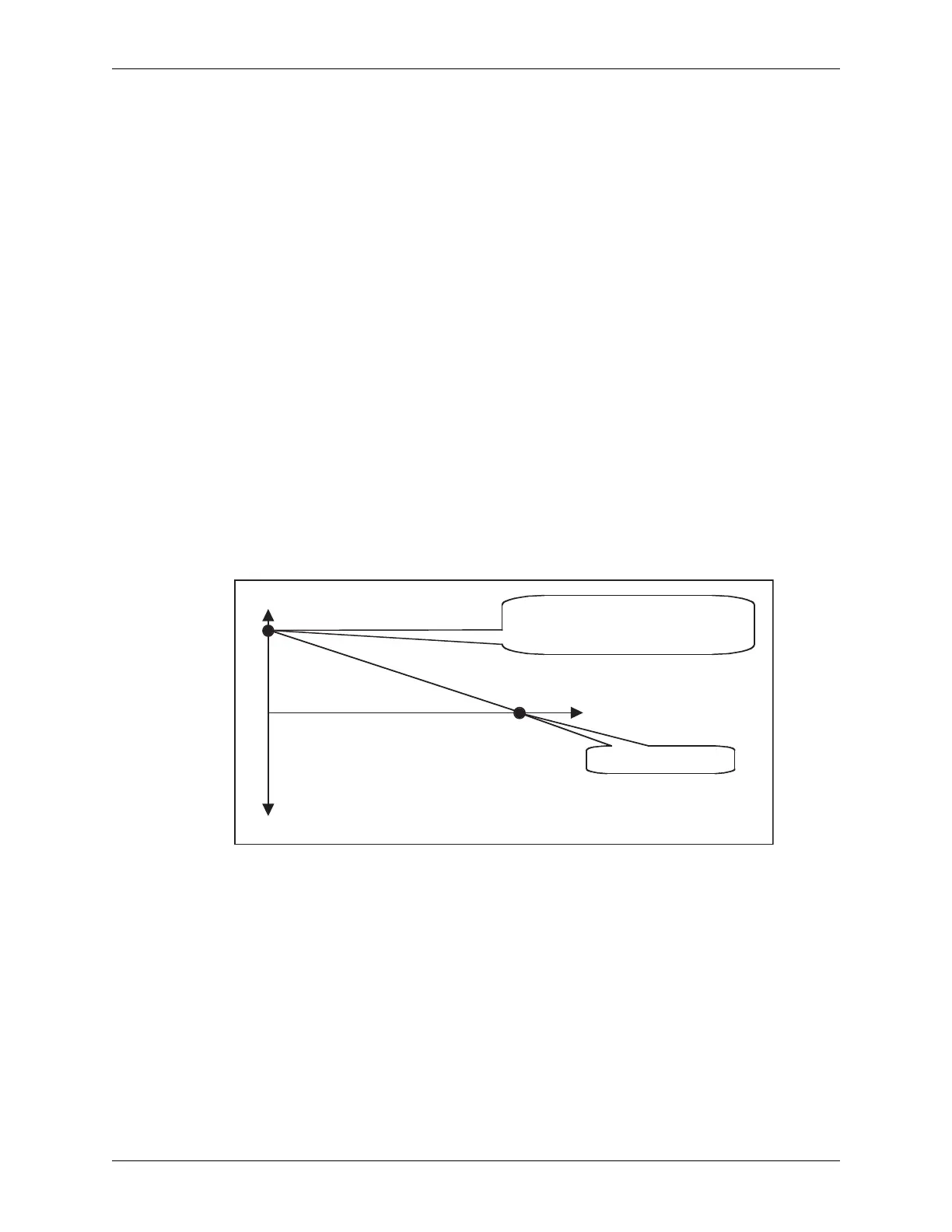
. See Figure 3-3.
Figure 3-3 Reactance, Impedance, and Power Factor
Once you know impedance, you can calculate the power factor. Power factor is the
amount of useful power used. Its value is always expressed as a decimal less than
one (e.g., 0.90 or 90%). Low power factor is inefficient. Welding with 10 kA at
65% power factor actually requires 15.4 kA. The formula is Power Factor = R÷Z.
Monitoring a weld control’s power factor over time indicates much about the
condition of the welding circuit. Over time, power factor will get higher, because
as a tool ages, its resistance increases. Because the weld control calculates power
factor and resistance for you, you can calculate impedance without knowing the
reactance of the secondary circuit. A large drop in power factor can indicate poor
connections that require maintenance.
L and C directly counteract each other.
This value represents the difference
between them.
Pure Resistance Value
L
C
Z
R
 Loading...