TROUBLESHOOTING
Spot Welding Manual for Medar 5-6 MOTOMAN
• Use a rubber mallet to align holder and tips, instead of a metallic tool.
• Avoid leaving electrodes unused in tapered holder seats for long periods of
time.
• Use a tip dresser on a regular basis to maintain correct electrode contour.
Never dress an electrode using a coarse file.
• Clean the tip taper and holder taper on a regular basis, removing foreign
materials.
• To simplify tip removal and avoid tip damage, coat the tip with a thin film of
cup grease before placing it in the holder. Use ejector-type holders to avoid
damaging tip walls. Never use pipe wrenches or similar tools when removing
electrodes.
5.5 Troubleshooting Dual Port RAM I/O
If a communication problem occurs in the XRC-to-Medar spot welding interface,
use the dual port RAM memory I/O information in Tables 5-4 and 5-5 to
troubleshoot the problem. These tables list the concurrent I/O addresses used to
check the status of the dual port RAM inputs and outputs. The dual port RAM
interface consists of M-registers, which are copied to and from the auxiliary
addresses shown in the tables.
Execute the SPOT command and verify the following I/O definitions:
1. Weld sequence numbers 7100 - 7107 should pulse in a non-zero bit pattern.
2. Critical outputs should be defined as follows:
• 7120 = 0
• 7121 = 0
• 7123 = 1
• 7124 = 1
• 7157 = 1 (MFDC only)
3. Critcal inputs should be defined as follows:
• 7221 = 1
• 7222 = 0
• 7257 = 1 (MFDC only)
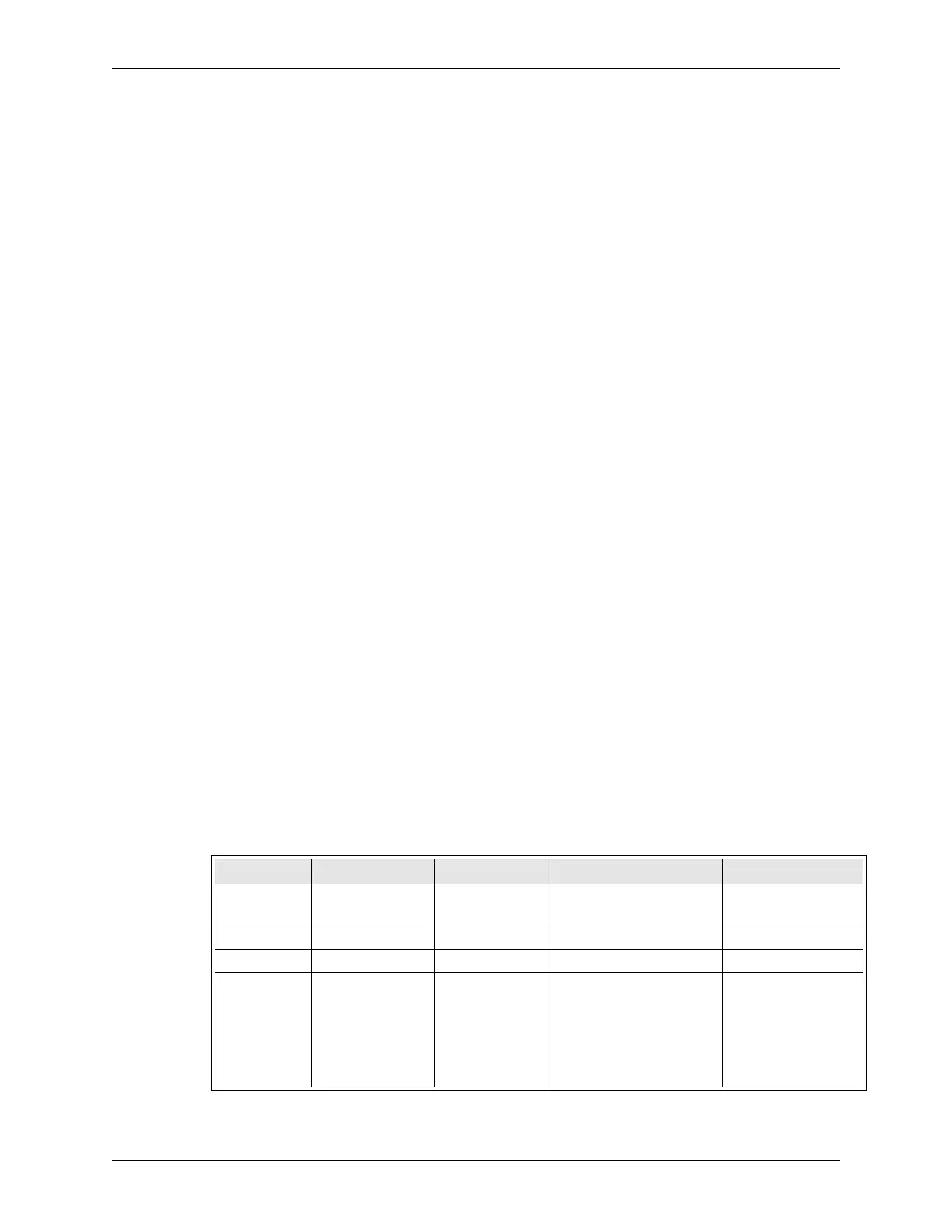
Table 5-4 XRC Outputs to Medar Board
Byte M-Resister AUX Address Description I/O Definition
Host Count M000 High Byte 7110 - 7117 Counter to verify commu-
nication.
Increments 0 to
65535
Sequence # M000 Low Byte 7100 - 7107 Weld Sequence Number 1 to 255
Stepper Reset M001 High Byte 7130 Stepper Reset 1 = Active
Control 1 M001 Low Byte 7120
7121
7122
7123
7124
7125 - 7127
Control Stop
Isolation Contactor Status
Fault Reset
No Weld
Weld Initiate
Reserved
0 = Active
0 = Closed
1 = Active
0 = No Weld
1 = Initiate
-
 Loading...