-
Radio Power
4
Introduction This section of the manual provides a detailed circuit description of
the power distribution for an ASTRO Digital SABER radio.
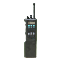
General In the ASTRO radio, power is distributed to three boards:
• transceiver
• VOCON
• display
In the case of a secure model radio, the encryption module is supplied
also.
Power for the radio is provided through a battery supplying a nominal
7.5Vdc directly to the transceiver. The battery is available in the
following forms:
• Nickel-Cadmium, High-Capacity (1100mAh),
Medium-Size Housing
• Nickel-Cadmium, High-Capacity (1100mAh),
Medium-Size Housing (FM Approved, Submersible)
• Nickel-Cadmium, Ultra-High Capacity (1800mAh),
Large-Size Housing
• Nickel-Cadmium, Ultra-High Capacity (1800mAh),
Large-Size Housing (FM Approved)
• Nickel-Cadmium, Ultra-High Capacity (1800mAh),
Large-Size Housing (FM Approved, Submersible)
• Nickel-Metal-Hydride, Medium-Capacity (950mAh),
Small-Size Housing
• Nickel-Metal-Hydride, Ultra-High Capacity (1650mAh),
Medium-Size Housing (FM Approved, Submersible)
B+ from the battery is electrically switched to most of the radio, rather
than routed through the on/off/volume control knob, S901/R901. The
electrical switching of B+ supports a “keep-alive” mode. Under
software control, even when the on/off/volume control knob has been
turned to the “off” position, power remains on until the MCU
completes its power-down, at which time the radio is physically
powered-down.

 Loading...


