10-8
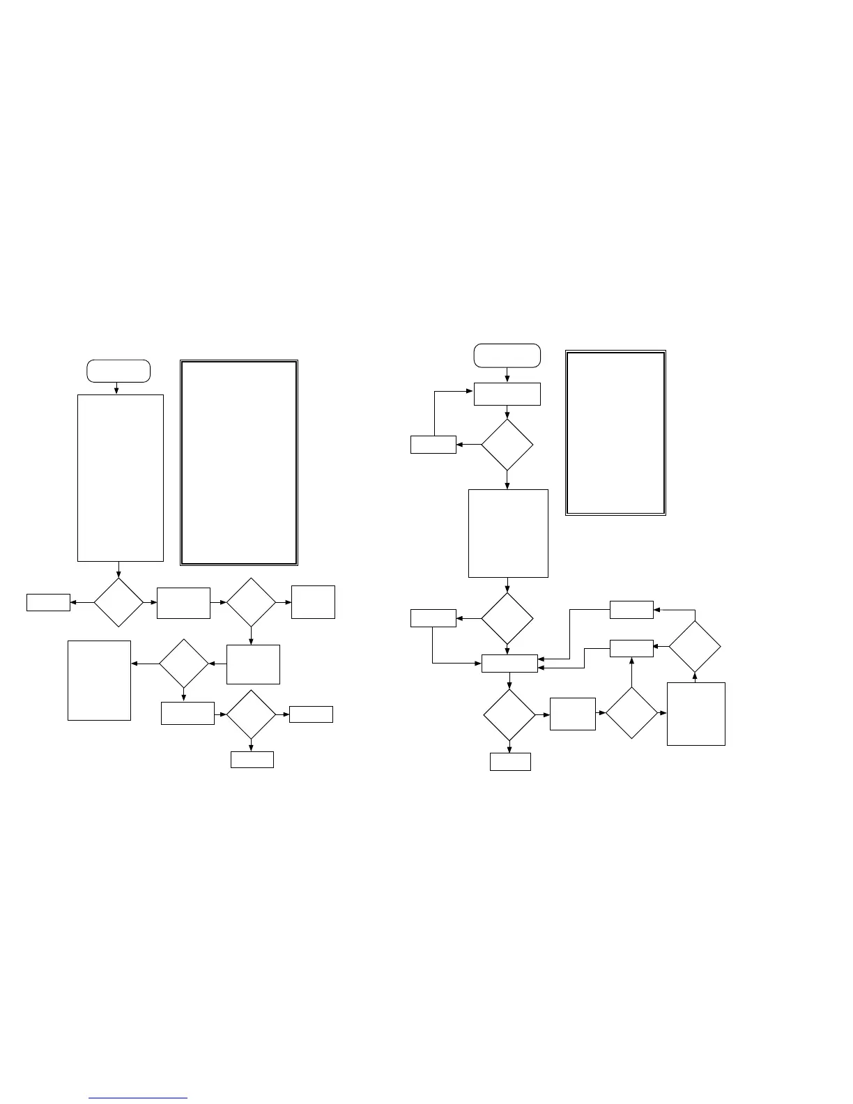
Chart 11 . 02/A0, ADSIC Checksum Faiure
Synopsis
The ADSIC calculates a checksum of the
configuration bus data programmed
through the Host µC SPI interface. This
failure indicates some problem with the
data. It should be noted that this is a
non-fatal error as it happened. As the
ADSIC controls some of the functions of
the DSP memory mapping and
interrupts, some aspects of ADSIC
programming problems may cause a
general DSP hardware failure. Some
operation of the ADSIC can be
determined by looking for the 8KHz @
IRQB. This signal is present only after
the host µC has programmed the IC.
Partial operation of the device may point
to a missing supply connection. Basic
failure modes are as follows:
1) An open or short in the DSP address
or data bus and select lines may cause
an error in reading the checksum.
2) Missing or improper 2.4 MHz clock
reference.
3) Missing signal in the Host µC SPI
programming interface.
4) Open or missing analog or digital
supply at one or more IC pads.
5) General IC failure.
Fail 02/A0
ADSIC Checksum
Failure
Use ohmmeter to electrically
verify following signal
connections to source IC:
Signal @ U406 Source
D8-D23 U405
A0-A2,A13-A15 U405
PS*,RD*,WR* U405
SELx,RSTx U204
SPD,SCLK U204
1
VDDD,VDD1,VDD2,
VDD3 +5V
VDDAb,VDDA +5VA
VSSD,VSS1,VSS2,
VSS3 GND
2
VSSA,VSSAb AGND
ABI R402
1
Note: Finding an open at VDDx
may be difficult because of low
isolation between supply pins.
2
Also measure continuity
between GND and AGND through
jumper JU407.
Connections
good?
Repair opens.
No
Verify 2.4MHz
reference clock at
U406 IDC per Fig.
W10
Clock
Present?
Verify SPI
programming
signals per Fig.
W6. initiated by
mode change.
Programming
signals
verified?
Verify U406-
RSTx goes high on
initial power up.
Reset high?
Replace U406.
Verify clock at
ABACUS
source and/or
fix connection.
Verify SPI operation
by verifying
programming of
synthesizer IC
initiated by a channel
change. If pass find
connection problems to
U406. A failure
indicates a software
problem or hardware
fault with U204.
No
Yes
Yes
No
Yes
MAEPF-24416-A
No
Yes
Replace U204.
Chart 12 . 02/81, DSP ROM Checksum Failure
At radio power up,
verify U404
A14,A15,A16
transisiton to a high
logic state. Verify
activity(transitions
from high to low)
on U404 - CE*.
Use ohmmeter to
electrically verify
following signal
connections to source IC:
Signal @ U404 Source
D0-D7 U405
A0-A13,A17 U405
A14-A16 U406
CE* U406
OE*,WE* U405
VCC +5V
VSS GND
Replace U404
ADSIC
Good?
Replace U406
No
Yes
DSP ROM
ReFLASH
passed?
End
No
Yes
Repair opens.
Fail 02/81
DSP ROM Checksum
Failure
Visually inspect all
leads to U404 with
a 5x glass.
Connections
good?
No
Yes
Connections
good?
Repair opens.
Yes
No
Go to section
on ADSIC
Checksum
Failure (02/A0).
Chart C.11
ADSIC
Good?
Yes
MAEPF-24417-A
ReFLASH DSP
ROM
No
Synopsis
This failure indicates the DSP
ROM program code is incorrect.
It is implied that the DSP found
and executed enough valid code
at power up to get to the point
of verifying the rest. Basic
failure modes are as follows:
1) The contents of U404 has
been corrupted.
2) The decoding logic comprised
of U405 and U406 is not
working properly due possibly
to circuit opens or shorts or
that a failure of one or more of
these ICs has occurred.
3) U405 has failed.
Due to the fact that the DSP
successfully initialized, a
failure in one of the ICs is not
likely.
 Loading...


