-
Controls and
Control Top Flex
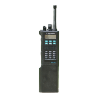
The control top controls include an on/off switch, volume, 16 position
mode select switch with two position toggle, and ergo code/clear mode
switch with additional emergency switch. The side controls include
three momentary push button switches (monitor, RAT1, RAT2) and
PTT. These components are connected through a flex circuit to the
controller at J901, see Figure 11.
UNSW_B+ is routed through S901 to provide the B+_SENSE signal
which provides radio power control. Refer to the power distribution
section for further details.
Volume control is provides by R901 which is a potentiometer biased
between +5Vdc and ground. The VOL signal is a voltage level between
+5Vdc and 0Vdc dependent on the position of the rotary knob. VOL
is an input to an A/D port on the MCU (U204). The MCU sends the
appropriate message to the DSP to adjust speaker volume based on this
setting.
Switch S903 is the two-position programmable switch typically used
for code or clear mode selection. It is an input to a control I/O with a
pull up resistor so the logic defaults high. Selecting clear mode pulls
this signal to a logic low. Appropriate operation is configured by the
MCU. In addition, this switch contains an additional momentary
button typically used for emergency. This button is connected along
with the PTT, and programmable side buttons on a resistor divider
network biased between +5Vdc and ground. This network made up of
R902, R903, and R904 provides a voltage level to an A/D port on the
MCU dependent on which button is pressed. The MCU determines
which button is pressed based on the value at the A/D port.
Figure 11 . Control Top Flex
R902
91K
R904
150K
SB1
(MON)
SB2
SB3
S903 TOP BUTTON
PTT
1
2
4
8
B
S902
Zone/Channel
Select
C
C
A
R901 VOL
S901
ON/OFF
1
2
3
45
UNSW_B+ (1)
+5V (5)
PROG_SWITCH (2)
VOL (3)
EMERG (4)
B+_SENSE (10)
GREEN_LED (8)
RED_LED (12)
INT_PTT* (6)
RTA0 (11)
RTA1 (13)
RTA2 (15)
RTA3 (7)
A/B SWITCH (9)
DGND (14)
CR901
RED
CR902
GREEN
1
2
3
To Controller
J901
R903
68K
MAEPF-24345-O

 Loading...


