-
RX Signal Path The vocoder processes all received signals digitally. This requires a
unique back end from a standard analog radio. This unique
functionality is provided by the ABACUS IC with the ADSIC (U406)
acting as the interface to the DSP. The ABACUS IC located on the
transceiver board provides a digital back end for the receiver section.
It provides a digital output of I (In phase) and Q (Quadrature) data
words which represent the IF (Intermediate Frequency) signal at the
receiver back end (refer to appropriate transceiver section for more
details on ABACUS operation). This data is passed to the DSP through
an interface with the ADSIC (U406) for appropriate processing.
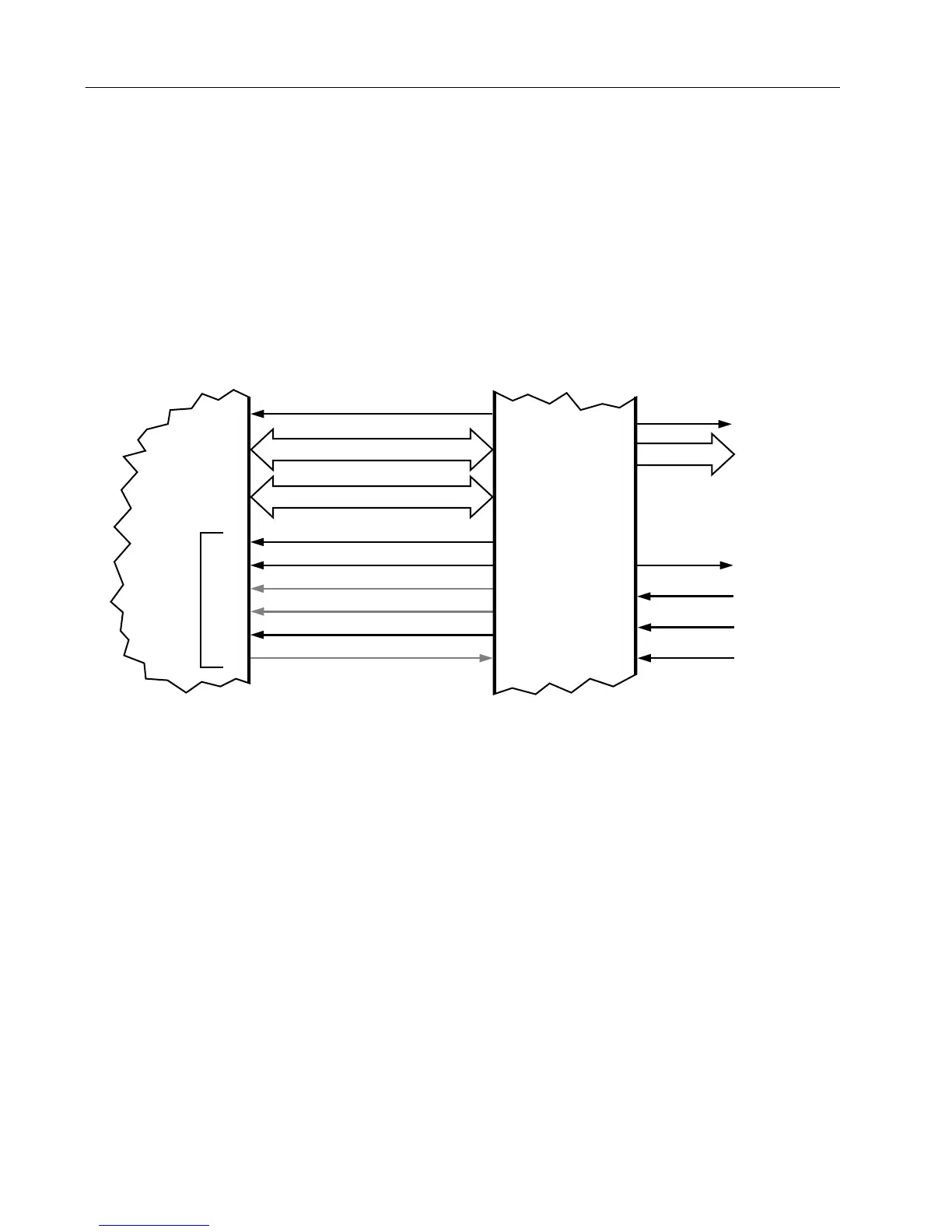
The ADSIC interface to the ABACUS is comprised of the four signals
SBI, DIN, DIN*, and ODC (refer to Figure 6).
NOTE: An asterisk symbol (*) next to a signal
name indicates a negative or NOT logic
true signal.
ODC is a clock ABACUS provides to the ADSIC. Most internal ADSIC
functions are clocked by this ODC signal at a rate of 2.4MHz and is
available as soon as power is supplied to the circuitry. This signal may
initially be 2.4 or 4.8MHz after power-up. It is programmed by the
ADSIC through the SBI signal to 2.4MHz when the ADSIC is initialized
by the MCU through the SPI bus. For any functionality of the ADSIC
to exist, including initial programming, this reference clock must be
present. SBI is a programming data line for the ABACUS. This line is
used to configure the operation of the ABACUS and is driven by the
ADSIC. The MCU programs many of the ADSIC operational features
through the SPI interface. There are 36 configuration registers in the
ADSIC of which four contain configuration data for the ABACUS.
When these particular registers are programmed by the MCU, the
ADSIC in turn sends this data to the ABACUS through the SBI.
Figure 6 . DSP RSSI Port - RX Mode
48KHz TX Data Interrupt
Serial Transmit Data
Serial Receive Data
2.4 MHz Receive Data Clock
20 KHz RX Data Interrupt
1.2 MHz Tx Data Serial Clock
D8-D23
A0-A2,A13-A15,RD*,WR*
SCKR
RFS
TFS
SCKT
RXD
TXD
ADSIC
U406
GCB0-GCB3
To
Audio PA
U401
SDO
SC0
SC1
SC2
SCK
SRD
STD
SSI
SERIAL
DSP56001
U405
IRQB
IRQB
8KHz
SBI
DIN
DIN-
IDC
ODC
Data In
Data In*
SBI
ABACUS II
Interface
J401-1
J401-2
J401-8
J401-4
MAEPF-24339-O
 Loading...


