10-10
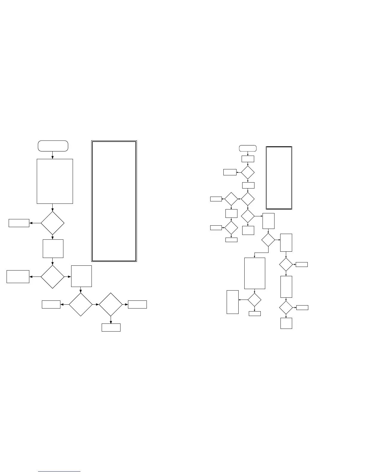
Chart 15 . 02/82, DSP External SRAM Failure U402
Does a fault
exist with
U403?
MAEPF-24408-B
Yes
Refer to a
Fail 02/84.
Replace U402.
Do all three
SRAMs
exhibit a
fault?
Replace U405.
Yes
No
No
Connections
good?
Repair opens.
Yes
No
Check for
ADSIC
programming
checksum
error.
Use ohmmeter to
electrically verify
following signal connections
to source IC:
Signal @ U402 Source
D0-D23 U405
A0-A12 U405
WR*,RD* U405
E1* U405-A15
E2 U405-A13
X/Y*,V/S* GND
VCC +5V
VSS GND
Synopsis
On power up the DSP writes
data to the device and then
verifies the data. This failure
indicates the DSP SRAM failed
this pattern/checksum test.
U402 decoding logic consists
entirely of address lines from
the DSP (U405). A failure in
this part would point to the
part itself or with the DSP.
However the possibility exists
for a decoding logic problem to
cause one of the other SRAMs
to overwrite U402. This is
particularly the case with
U403 which is selected with
the RSEL signal from ADSIC
(U406). This problem should
be investigated before
replacing any parts. Basic
failure modes are as follows:
1) Some problem exists
(open/shorts) with the
external address/data bus.
2) Possible failure of the DSP
address/data bus or
RD*/WR*/PS*/DS* signals
used in selecting this part.
Since the other two DSP
SRAMs share this bus as well
as other ICs, this is not a likely
failure.
3) Open in supply or ground to
the IC.
4) Failure of the IC.
Fail 02/82
DSP SRAM U402
Failure
ADSIC
checksum
error?
Refer to
section on
Fail 02/A0.
Chart C.11
Yes
No
Due to the
possibilityof a
failure causing
a RAM overlap
U403 should be
verified.
Chart 16 . 02/90, General DSP Hardware Failure
Fail 02/90
DSP Hardware
Failure
Verify standard
bias per table
Table 3.
No
Isolate and
repair problem.
See Chart C.5
Yes
Standard
bias OK?.
Reflash DSP
code.
Unable to
Reflash
DSP code?
Fail
02/90
persists?
Verify Host Port:
Use ohmmeter to
electrically verify
following signal connections
to source IC:
Signal @ U405 Source
H0-H7 U204
HA0-HA2 U204
HR/W* U204
HEN* U204
RESET U204
On power up, verify
transitions on HEN* from
high to low indicating DSP
is being selected.
Synopsis
On power-up the host µC sends
several handshake commands
through the host interface to
the DSP system to coordinate
the power up programming of
the ADSIC and detect any DSP
power up status messages..
This error indicates the host
never received a response
from the DSP. The power up
code is downloaded from U404
and executed internally in the
DSP. This is a wide ranging
problem which may be difficult
to isolate without special tools.
Some basic failure modes:
1) Some fundamental system
clocks or supplies are not
operational.
2) Improper operation of the
ADSIC memory mapping
functions.
3) Corrupted DSP FLASH
program code.
4) Hardware problem with host
µC/DSP interface.
5) Improper configuration of
MODA and MODB by ADSIC.
6) DSP_RST* not operating
correctly.
7) ADSIC not functional due to
missing 2.4MHz reference.
Yes
No
No
Yes
End.
Verify D23 is
pulled high
through R404
at power up..
Replace U405.
D23 is
high?
Yes
No
Repair problem
with R404.
FLASH
programming
error
generated?
No
Refer to
section on DSP
ROM failure
(Fail 02/81).
Chart C.12
Yes
At power up
verify state of
MOD select
pins on DSP
when RESET
goes high:
MODA High
MODB Low.
MOD pins
correct?
Yes
No
Verfiy
operation and
continuity of
RSTx on U406.
On power up,
Signal should
transition
from low to
high.
ADSIC RESET
functional?
Replace U204.
No
Yes
Verify 2.4
MHz reference
on U406-IDC
per Fig W10.
*Note
frequency may
be off, if
sequence was
aborted before
ABACUS was
programmed.
Reference
present?
Yes
MAEPF-24414-A
No
Replace U406.
Verify
operation of
ABACUS IC
and repair as
necessary.
Host port
operation
verfied?
Repair opens
as necessary.
No activity
exists on
pins when
measured on
U204 at power
up may
indicate a bad
µC. If this is
the case
replace U204.
Replace U405.
Yes
No
 Loading...


