10-5
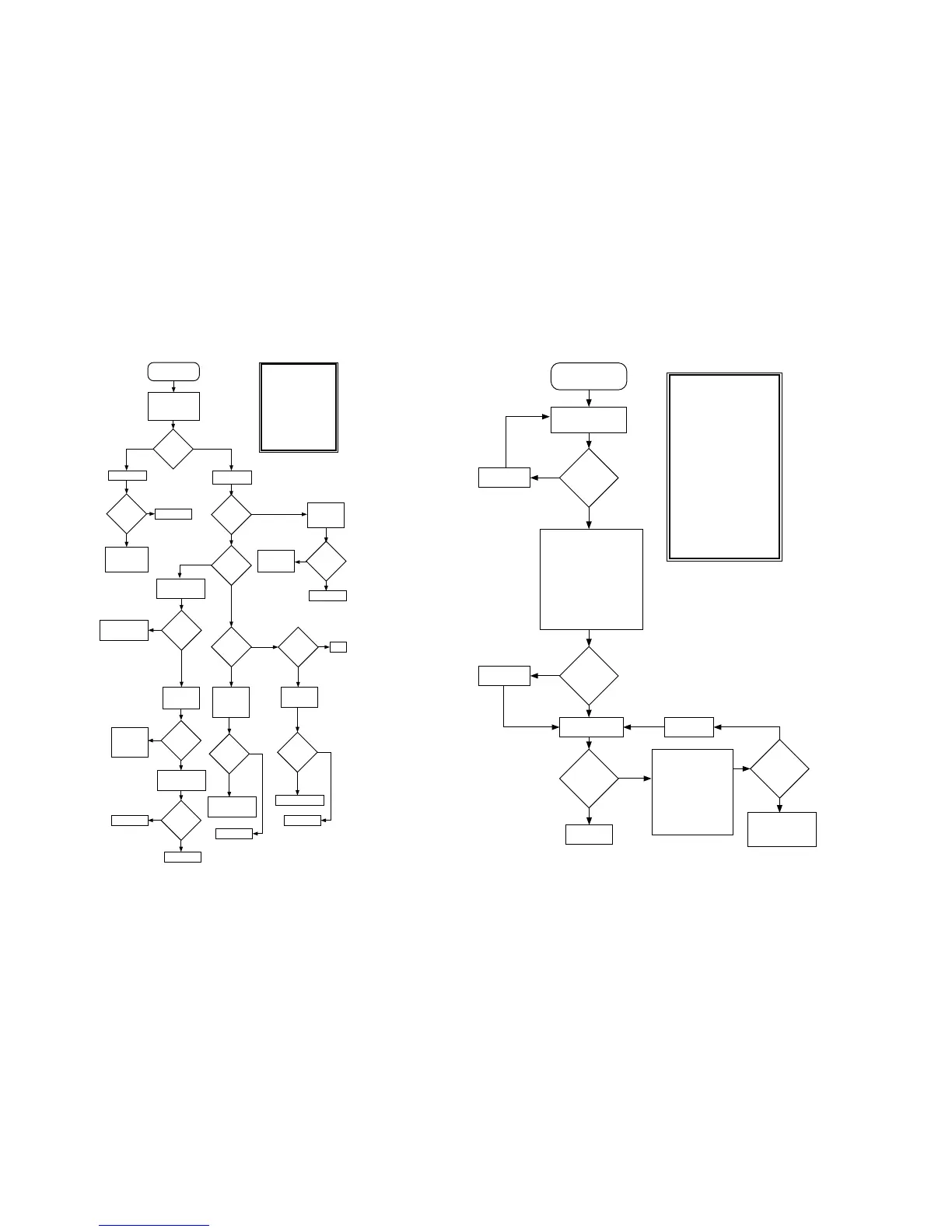
Chart 5 . DC Supply Failure
Is the
output on
U410-3
+5VDC?
No
Verify control
voltage at
Q207-4 is logic
low.
Control voltage
correct?
Check inverter
circuit of Q206
and R244.
No
Replace Q207.
Yes
Connect supply or
battery (B+) to radio
and turn
ON/OFF/VOLUME
CONTROL knob on.
Is B+ at
Q207-2?
DC Supply Failure
Synopsis
This failure implies a problem
with the DC power distribution.
It may relate to a battery
supply or one of the regulated
supplies. Basic failure modes
are as follows:
1) Fuse S1 blown.
2) Open in Battery contacts or
from flex circuit through J401.
3) Defective switch Q207.
4) Open in B+_SENSE through
control top switch or
B+_SENSE not detected by µC.
5) Defective +5V regulator.
Check fuse S1.
Replace fuse.Fuse good?
No
Locate and repair
open between
battery and VOCON
board.
Yes
Yes
No
Verify B+ at
Q207-5.
Is B+ at
Q207-5?
Is +5VDC ± 5%
at C470?
Yes
Verify U409-2
> 2VDC.
U409
switched
on?
Yes
Check
continuity of
B+SENSE to
U409 and R423
pull-up.
No
Verify L402 continuity
< 1 Ω and solder
connection to board.
Yes
Verify Lx signal per
Fig. W1.
U409 running?
No
Yes
Verify integrity of
CR403, C470, C463
and R436.
No
L402 good?Replace L402.
Replace U409.
Yes
No
Yes
No
End
Yes
No
Verify SW_B+
at input to
U202 and
RESET signal is
logic low.
Signals
verified?
Replace U202.
Repair connections
back to the vocon
board through J401.
Yes
No
Verify SW_B+
at input to
U410.
Replace U410.
Repair connections .
Yes
MAEPF-24399-O
No
Is the
output on
U202
+5VDC?
Signals
verified?
Chart 6 . 01/81 Host ROM Checksum Failure
Synopsis
This failure indicates the Host
ROM program code is incorrect.
It is implied that the host
processor found and executed
enough valid code at power up
to get to the point of verifying
the rest. Basic failure modes
are as follows:
1) The contents of U205/U210
have been corrupted.
2) The decoding logic comprised
of U204 and U206 is not
working properly due possibly
to circuit opens or shorts or
that a failure of one or more of
these ICs has occurred.
3) U205 or U210 has failed.
Due to the fact that the Host µC
successfully initialized, a
failure in one of the ICs is not
likely.
Repair opens.
Fail 01/81
Host ROM Checksum
Failure
Connections
good?
No
Yes
Visually inspect all
leads to U205 and
U210 with a 5x glass.
Check for operation of
U204 and U206 as
follows: During radio
power up Self-Test,
verify activity
(transisitons from high
to low) on U205/U210 -
ROM1CS*/ROM2CS*,
and OE*.
Use ohmmeter to electrically
verify following signal
connections to source IC:
Signal @ U205/U210 Source
HD0-HD7 U204
HA0-HA13 U204
HA14OUT,HA15OUT U206
HA16,HA17 U206
ROMCS1*,ROMCS2* U206
OE*,MEMR/W* U206
VCC +5V
VSS GND
Replace
U205/U210.
No
MAEPF-24421-A
Yes
Host ROM
ReFLASH
passed?
No
Yes
Connections
good?
Repair opens.
Yes
No
ReFLASH Host
ROM
End
Initial
operation
checks
Good?
Refer to section on
Power-up Failure C.3
and/or Fails to
Bootstrap C.4.
 Loading...


