Device
Analog
Input
Channel
Select
Figure
8-4.
Effective
Analog
Input
Inpedance
(During
Sampling
Only)
accuracy on the
AID,
VRH
should
be
equal to or
less
than VDD, VRL should
be
equal to or greater
than
VSS but
less
than the maximum specification and (VRH-VRU should
be
equal to or greater
than 4
volts.
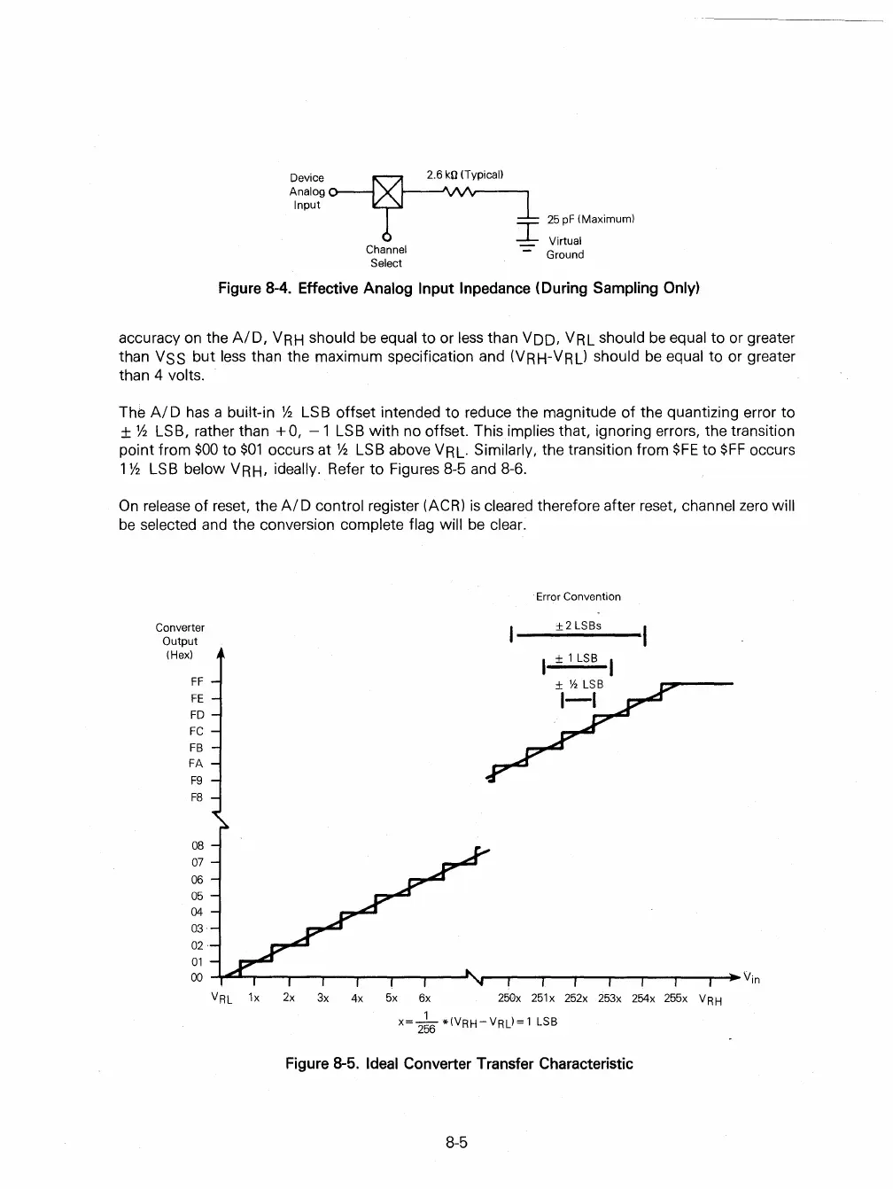
The
AI
D
has
a built-in
Y2
LS
B offset intended to reduce the magnitude
of
the quantizing error to
±
Y2
LSB, rather than +
a,
-1
LSB
with
no offset. This implies that, ignoring errors, the transition
point from
$00
to
$01
occurs at
Y2
LSB above VRL. Similarly, the transition from
$FE
to
$FF
occurs
1
Y2
LSB below VRH, ideally. Refer
to
Figures 8-5 and 8-6.
On
release
of
reset, the
AID
control register (ACR)
is
cleared therefore after reset, channel
zero
will
be
selected and the conversion complete flag will
be
clear.
Converter
Output
(Hex)
FF
FE
FD
FC
FB
FA
F9
F8
08
07
06
05
04
03
02
01
00
vRL
Error Convention
±2
LSBs
1x
2x
3x 4x
5x
6x
250x
251x 252x 253x 254x 255x vRH
x=_1_*(VRH-VRL)=1
LSB
256
Figure
8-5.
Ideal
Converter
Transfer
Characteristic
8-5
 Loading...

