Section 2, Installation and Setup
Chemgard Infrared Gas Monitor
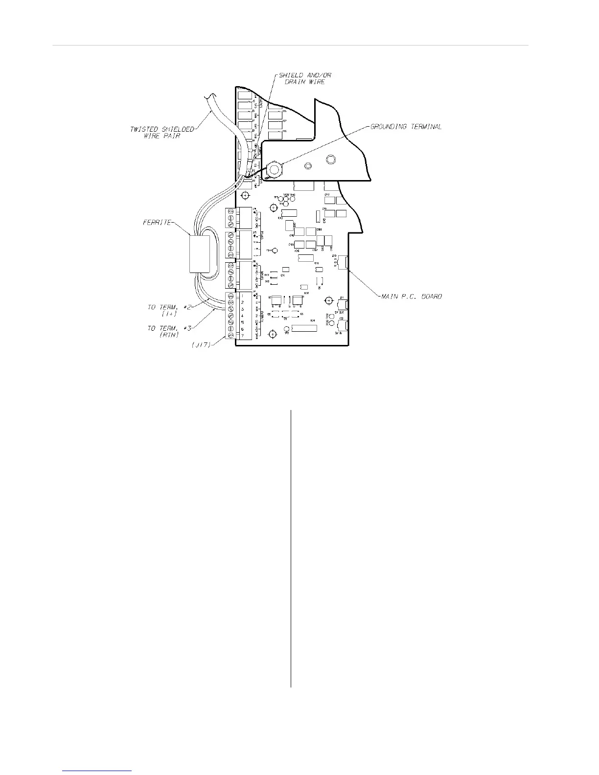
Figure 2-7.
Ferrite Bead Installation
NOTE: The maximum wire size that these
connectors can accept is #12 AWG.
Trouble Relay
There is one relay (the Trouble relay) within the
unit that indicates that a trouble or start-up
condition exists. This relay is configured from the
factory and operates differently than the alarm
relays. It operates in a normally-energized mode.
This relay is energized when the instrument is:
•
normally operating,
•
in the calibration mode, or
•
in the setup condition.
The relay is de-energized when:
•
a fault is detected,
•
the unit is in the start-up state, or
•
the main power is lost.
This means that power is no longer provided to
the relay coil. It is not possible to change the
configuration of the Trouble relay.
The relay connector function or identification:
•
NORMALLY OPEN (NO),
•
COMMON (COM),
•
NORMALLY CLOSED (NC)
as marked in FIGURE 2-6 refers to the relay
contacts as if the relay is de-energized or in the
trouble condition. A relay contact is provided
between the Normally Clo
sed (NC) and Common
(COM) position. This contact will be made in the
event that main power to the unit is lost or any
other trouble condition exists.
Trouble Relay Connection Wiring
The Trouble relay wiring should enter the unit
through one of the entries on the right side of the
unit. Connections are made at the internal
terminal strip labeled J29, positions 1, 2 and 3
(located on the right side of the circuit board -
FIGURE 2-6). The terminal portion of the
connector can be unplugged from the circuit
board for ea
sier wire connections. The maximum
wire size that these connectors can accept is
#12 AWG.