Appendix C, RS-232 Output
Chemgard Infrared Gas Monitor
Table C-7. Function of Switches
SWITCH
SWITCH
POSITION
DESCRIPTION
INITIALS
1
ON
Enables the password
option
1
OFF
Disables the password
option
2
ON
Set the password
2
OFF
Normal operation
3
ON
Resetting alarm without the
password
3
OFF
Password is necessary to
reset alarms
4
ON
Remote Front Panel
connected
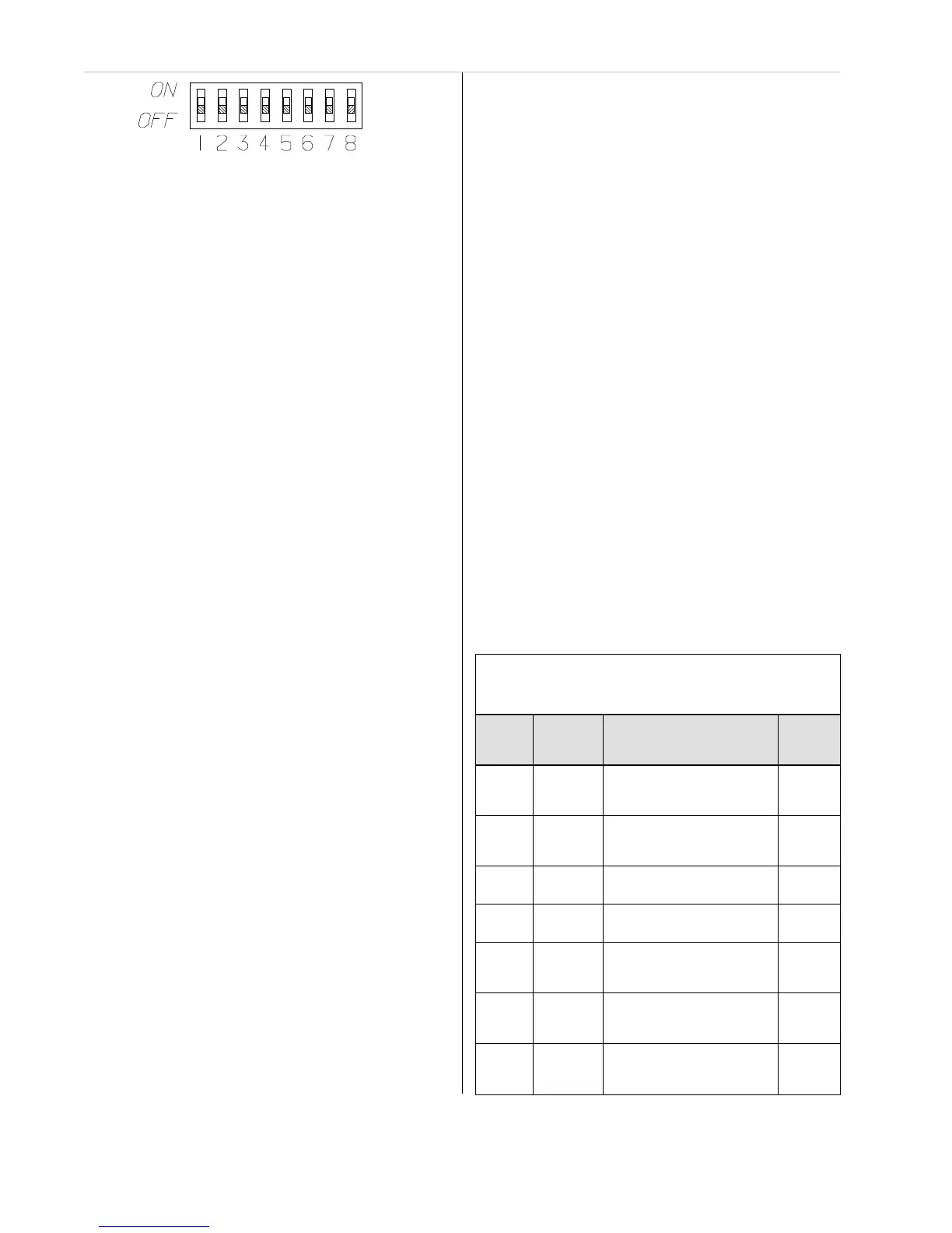
Figure C-6. Password Enabling Switches
2. On the inside of the front door, locate the four
front cover nuts securing the metal cover
(FIGURE C-4).
3. Unscrew and remove these four front cover
nuts and lift off the metal cover.
4. Locate the bank of switches on the printed
circuit board exposed when the front cover
is removed (FIGURE C-5).
5. Each switch is labeled with its number and its
position. FIGURE C-6 also shows the
switch bank with its numbered switches.
•
Each switch in this bank activates a
different feature.
•
TABLE C-8 describes each switch and
its function.
•
Read, mark and initial each function you
are going to use.
6. To enable the password option, set switch 1 to
the ON position.
7. To set or change the password, put switch 2 in
the ON position.
•
The front panel display shows:
•
the word SET and
•
the new password.
To change the password, press three
buttons on the front panel.
•
The password will be the last three letters
displayed on the front panel display.
•
The button sequence is stored when
ENTER is pressed.
After selecting the password, return this
switch to the OFF position.
NOTE: The password must be
re-entered when:
•
the unit is de-energized
•
a bad or wrong password is entered
•
a loss of communications is detected
between the Chemgard Infrared Gas
Monitor and any optional Remote
Front Panel
•
no password is entered within the
last hour.
8. Switch position 3 allows the following
without entering the password:
•
resetting latched alarm relays
•
silencing the audio output.
When setting Switch 3 to the ON position
while an audio alarm or a latched relay can
be reset, the followi
ng message displays:
•
MAIN RESET ALARM.
9. Switch 4 enables communication between
the Chemgard Infrared Gas Monitor and a
Remote display.
•
When a loss of communications occurs
with the Remote Display within 3.5
seconds, the following message displays:
•
LOSS OF COMMUNICATION.
•
This switch position also allows the
Remote Display speaker to follow
the Chemgard Infrared Gas Monitor
speaker operation.
10. Switch 5, in the ON position, allows the
audio output to automatically reset if the
Chemgard Infrared Gas Monitor audio
output is reset.
•
Normally, if the Remote Display audio
output is energized, it is latched ON until
any panel key is pressed.