Chemgard Infrared Gas Monitor
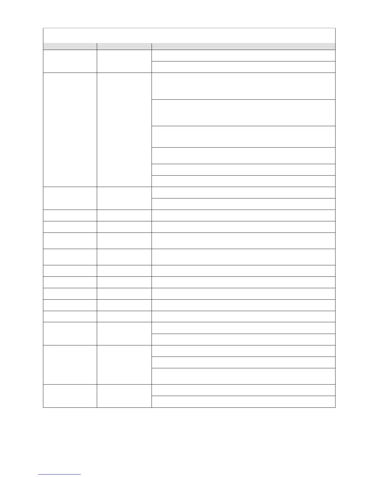
Table 5-2. Troubleshooting Guidelines
Start bypass flow
failed
Leaky or blocked
bypass line at startup
of unit
1. Same as bypass flow failure. Check as above, turn unit off and restart unit.
2. Leak test the flow system and restart unit.
Sensor flow failed
Leaky or blocked
sample line
1. Remove all input lines to the unit.
Attach one line at a time to check for sample input.
Check all end of line filters. Sample flow failure is always the present point
being sampled.
2. Remove the optical bench cover.
Check the inlet fitting, tubing, sample filter, tubing to the optical bench inlet
fitting, outlet fitting from the optical bench, sample pressure switch, and sample
manifold tubing.
3. Check the sample pressure switch for 4 VDC ON and OFF switching.
Check the cable terminals and plug end at press/sample connector.
Replace pressure switch if necessary.
4. Check operation of all manifold sample valves.
Check the optical bench inlet and outlet valves.
5. Check the optical bench inlet and outlet valve connectors on J22 and J21.
6. Leak test the flow system.
Start sensor flow
failed
Leaky or blocked
sample flow line at
unit startup
1. Same as sensor flow failure. Check as above; turn unit OFF and re-start unit.
2. Leak test the flow system.
Case temperature
Main board
1. Return to MSA for service.
Case temperature
Case temperature is
o
1. Return to MSA for service.
Thermostat sensor
failed
Controls optical
bench inside
1. Replacement of optical bench requires MSA service.
Sensor temperature
range failed
Checks for
temperature range of
o
1. Replacement requires MSA service.
Humidity sensor failed
Checks H
2
O sensor
1. Return to MSA for service.
Infrared source failed
Checks the I of
1. Return to MSA for service.
Photo synchro failed
Checks the chopper
1. Return to MSA for service.
PA IR sensor failed
Checks the sensor
1. Return to MSA for service.
Memory protect
Checks checksum
1. Return to MSA for service.
External reset failed
Checks the external
reset button
1. If not used, check for jumper between RST minus and RST plus on J16.
2. If used, verify switch is wired normally closed.
Display failure
Display
communications
1. Check RS485 connector on J15, terminals 1 and 2.
2. Check for broken or cracked display.
3. Remove rear panel cover and check cables between the display and the
display board.
Audio alarm failure
Audio alarm
1. Check output terminals 6 and 7 on J17.
2. Check for faulty horn buzzer.