• is mounted where the gas
is expected to exist
• is mounted with the sensor
pointing downward via the
3/4" NPT threads located
on the end of the
module, opposite the
sensor
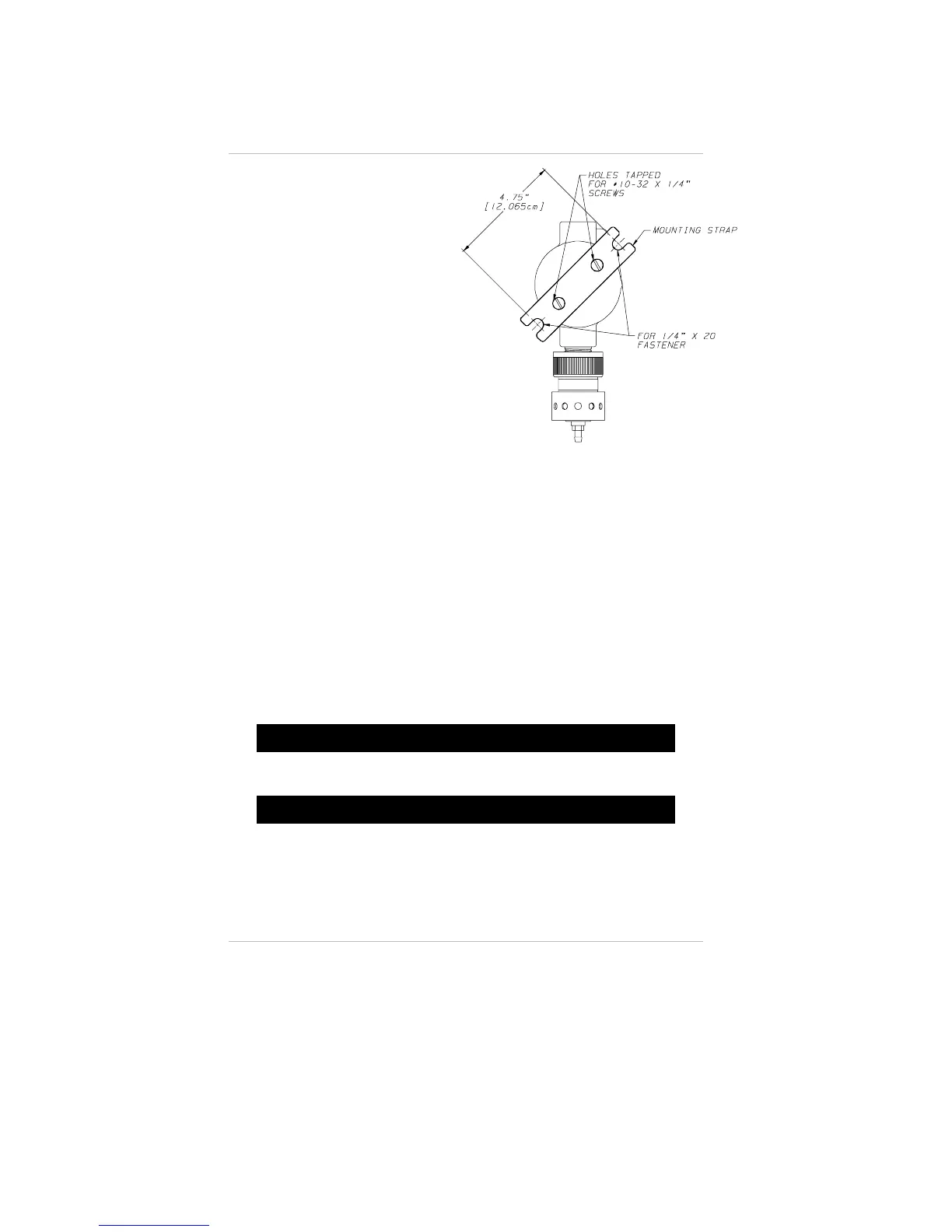
• can also be mounted with
the mounting strap (P/N
655700); see FIGURE 1-5
• wiring is routed to the
Toxgard II Monitor.
Permanently connect 3/8" OD
tubing to the center post of
the sensor inlet. Route this
tubing to the Toxgard II
Monitor, ensuring there are no
kinks, leaks or other
obstructions. Secure this tubing near the monitor; it is used to
deliver check gas to the sensor module during calibration.
Electrical Connections for Toxgard
II Monitors
• Recommended wire is three-conductor, 16 gauge (12 gauge
maximum).
• Install an external switch or circuit breaker close to the unit for
disconnection purposes.
• Install an over-current protection device (e.g., fuse) in the
supply wiring to the unit; two-amp, slow acting fuses
are recommended.
"
WARNING
Before wiring the Toxgard II Monitor, disconnect power source
supplying the monitor; otherwise, electrical shock could occur.
"
CAUTION
Make all wiring connections and conduit runs according to accepted
commercial wiring practices. Install the Toxgard II unit in compliance
with the applicable requirements of the National Electrical Code
and/or any other local code requirements.
NOTE: For Toxgard II with Digital Output Monitors, see
manual (P/N 711203) for wiring instructions.
Figure 1-5.
Remote Sensor Mounting Method
Chapter 1, Set-up
1-10
 Loading...