3. Identify the sensor element needed and obtain the same
type of sensor element.
4. Toxic or Oxygen Sensors:
Unplug the sensor by pulling it straight down; properly
dispose of sensor.
Combustible Sensors:
• Combustible units have a three-pin connector; pry out the
locking clip and pull apart the connector (FIGURE 5-5).
5. Toxic or Oxygen Sensors:
Before installing the sensor, check the pins of the sensor
for a shorting clip; remove the shorting clip and the label
beneath the clip before installing the sensor. Install the
new sensor by aligning the pins; do not force onto pins.
Combustible Sensors:
Connect the three-pin connector on the new sensor
(FIGURE 5-5). Carefully reconnect the union, taking care
not to pinch the wires.
"!
CAUTION
Do not over-tighten the sensor on the inlet fitting; otherwise, damage
to the sensor may result.
8. Re-apply power to the Toxgard II Monitor.
9. Perform the INITIAL Calibration Procedure as outlined in the
Toxgard II Monitor Calibrator or Toxgard II Monitor
Controller instruction manual. This procedure differs
slightly from a standard calibration procedure. Use of the
INITIAL calibration procedure upon installation of a new
sensor ensures the Toxgard II Monitor will perform a
successful calibration. Failure to do so may result in a
CAL FAULT reading (FIGURE 5-6).
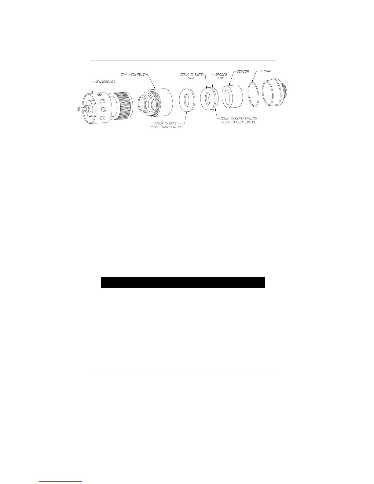
Figure 5-4.
Cap Location for Remote Toxic Gas or Oxygen Explosion-proof Sensor
Chapter 5, Maintenance
5-4
 Loading...