GB
MSA DESCRIPTION
ULTIMA
®
X
3 TM
9
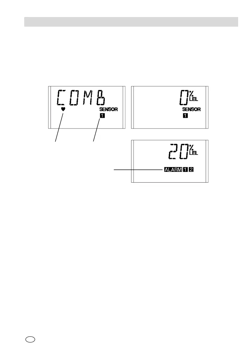
2.2. Components
Display
The display cycles through each connected sensor showing the gas type, gas
concentration and sensor number.
Fig. 2 Sensor Display View
A Gas Type Display 1 Heartbeat - acknowledges commu-
nications activity from ModBUS or IR
Controller/Calibrator command
B Gas Concentration Display 2 Sensor Number
C Gas Concentration Display with Alarm
Indication
3 Alarm Levels
Gas alarm conditions are shown by ALARM and the corresponding number of the
alarm level that is activated.
The display will latch on a gas alarm or fault condition and requires to be reset by
the user to resume cycling.
If multiple conditions exist, acknowledging one condition will reveal subsequent
alarm/fault conditions. Display cycling of sensors will resume when all conditions
have been reset
A
B
C
1 2
3