GB
INSTALLATION MSA
12 ULTIMA
®
X
3 TM
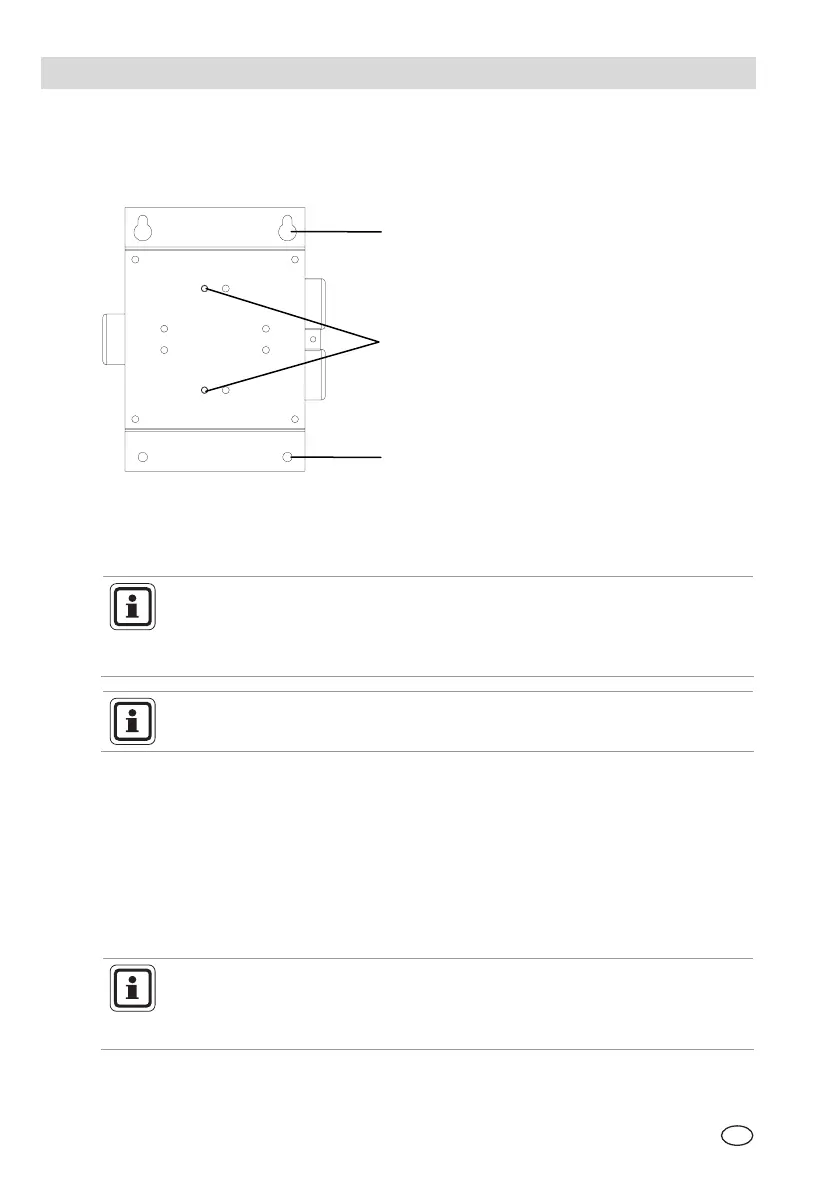
3.2. Installation with Mounting Kit
ULTIMA
®
X
3 TM
Gas Monitors are installed at the place of installation on a
mounting plate.
Fig. 3 Mounting plate
1 Wall mounting fixing holes
2 Instrument fixing holes
Use Ø6 x 20 mm screws and suitable plugs for attaching the mounting
plate to the wall.
M6 x 20 screws will also be required for fixing the mounting plate to the
ULTIMA
®
X
3 TM
Gas Monitor enclosure.
When preparing the assembly, make sure that the mounting
arrangement is correct for the particular instrument type.
Mount the instrument as follows:
(1) Using the mounting plate as a template, mark the holes for the four fixing
screws.
(2) Drill four holes of appropriate diameter.
(3) Attach mounting plate to the Gas Monitor enclosure with M6 x 20 screws.
(4) Attach Gas Monitor with mounting plate, using four
Ø6 x 20 screws, at the
place of installation.
During assembly, the ULTIMA
®
X
3 TM
Gas Monitor enclosure can be
rotated 360°, to ensure easy access to any of the four cable entries. For
correct positioning of the display, the electronics assembly can be
installed in any of the four self-aligning positions.
2
1
1