GB
MSA ELECTRICAL INSTALLATION
ULTIMA
®
X
3 TM
27
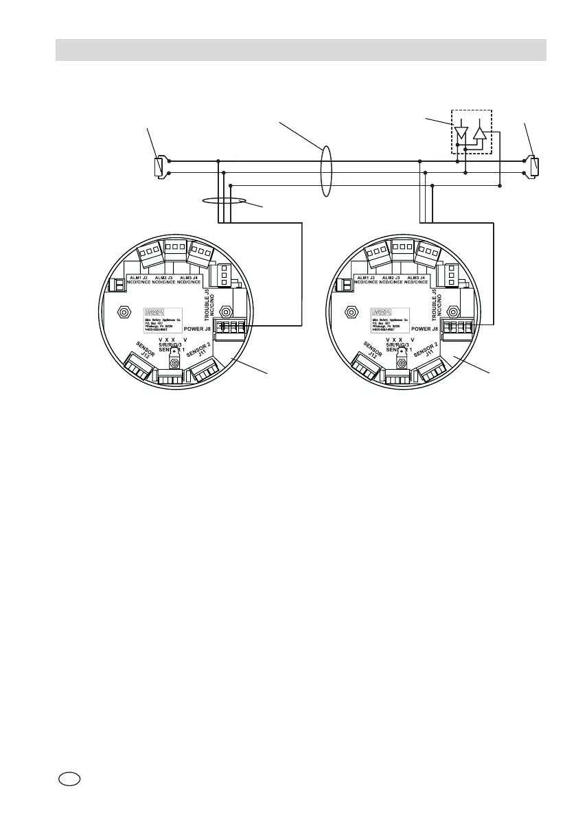
A-3. Connection Drawings
D
R
ACKNOWLEDGE
PUSHBUTTON
J10
ACKNOWLEDGE
PUSHBUTTON
J10
Fig. 6 Typical Communications Wiring Scheme
A Network Trunk 1 Line Terminal
B Network Branch 2 Master
C Transmit + / Receive + 3 Slave 1
D Transmit - / Receive - 4 Slave n
E Common
B
A
2
C
D
E
1
1
3
4