GB
MSA ELECTRICAL INSTALLATION
ULTIMA
®
X
3 TM
25
Appendix A Electrical installation
A-1. Installation Drawings
The cabling and electrical installation must be carried out based on the
instrument types used.
Electrical installation details are given in the appropriate drawings. Please
refer to ULTIMA/ULTIMA X Operating Manual (Order No.: 10050078).
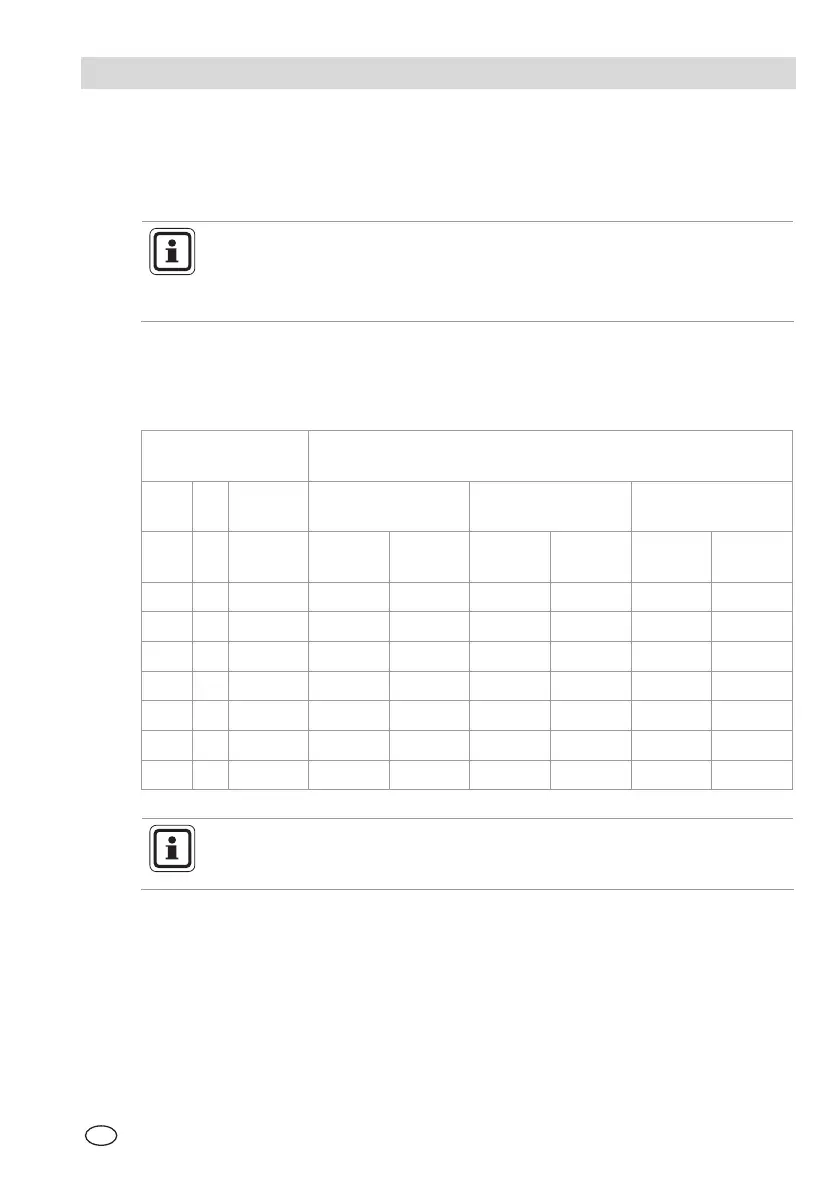
A-2. Cable Lengths and Power Consumption
Cable length
Maximum power cable length depends on sensor configuration and wire gauge.
Sensor
Configuration
Maximum Power Cable Length (metres)
(with Nominal 24-V DC Transmitter Supply)
CAT IR EChem
1.5 mm
2
Cable
[4.2 Ω per 300 m]
2.5 mm
2
Cable
[2.6 Ω per 300 m]
4 mm
2
Cable
[1.8 Ω per 300 m]
No
Relays
Relay
Option
No
Relays
Relay
Option
No
Relays
Relay
Option
0 0 3 1370 1065 2285 1675 3040 2285
0 2 1 605 45 835 760 1215 1065
0 1 2 910 685 1370 1065 1905 150
1 0 2 1065 835 1675 1295 225 1825
1 1 1 605 450 835 760 1215 1065
2 0 1 760 560 1065 910 1520 1215
3 0 0 605 455 835 760 1140 1065
As only one zener barrier can be installed in an ULTIMA
®
X
3 TM
enclosure, only one ‘reactive’ toxic gas sensor can be used with an
ULTIMA
®
X
3 TM
Gas Monitor.