GB
INSTALLATION MSA
14 ULTIMA
®
X
3 TM
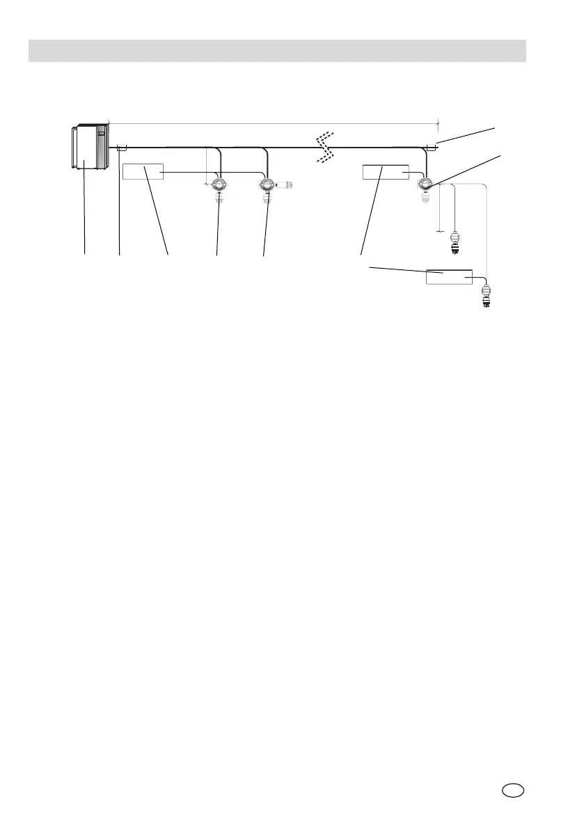
Fig. 4 Typical ModBUS Network Topography
A Communications Cable Trunk
B Communications Cable Branch
C Communications and Power Cables remote sensor
1 ModBUS Master Device
2 COM line termination device
3 DC or AC Power Source
4 Device 1
5 Device 2
6 Local DC or AC Power Source
7 Device n
8 COM line termination device
7
4 5
B
C
2
3 6
8
1
A