FunctionDescriptionKey
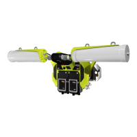
Power indicator LED3
• Green: when power is applied to the NS50.
• Red: when the power drops below 12V.
Status indicator LED4
• Flashing Red: startup in progress.
• Flashing Green: normal operation.
• Solid Red: indicates an error.
•
Off: indicates a problem (Refer to the Troubleshooting
Guide on page 93).
RP-TNC jack for connecting an antenna to Radio 2.MAIN antenna port for Radio 25
RP-TNC jack for connecting an antenna to Radio 2.AUX antenna port for Radio 26
Fibre port Link / Activity status
LEDs
7
• The top LED (green) ashes when data is transmitted or
received, and is solid when a link is established.
• The lower LED (orange) is active when the link is
running at 1Gbps.
Labelling of the Ethernet ports.External Ethernet port number8
External Ethernet with IEEE 802.3af PoE supply capability
for powering WAPs and other network devices.
External Ethernet ports9
External Ethernet port (9) Link /
Activity status LEDs
10
• The top LED (green) ashes when data is transmitted or
received and is solid when a link is established.
• The lower LED (orange) indicates that PoE power is
being supplied.
RP-TNC jack for connecting an antenna to Radio 1.MAIN antenna port for Radio 111
RP-TNC jack for connecting an antenna to Radio 1.AUX antenna port for Radio 112
A protective cover for the Ethernet port when it is not in
use.
Ethernet port protective cover13
Radio Link / Activity status LED14
• The top LED (green) ashes when data is transmitted or
received and is solid when a link is established.
• The lower LED (orange) ashes when a Wi-Fi tag is
detected by the radio card.
A protective cover for the antenna port when it is not in use.RP-TNC antenna jack protective
cover
15
Reset button for the unit. It will cause power to cycle without
losing the device conguration.
Reset button16
Button to reset Radio 1's conguration back to factory
defaults. Refer to Manual Reset and Reboot on page 40 for
details.
Default button for CPU 117
NS50 User Guide15Revision C
Understanding the NS50 Wireless Network Switch

 Loading...