IllustrationProcedureStep
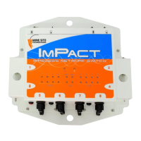
Insert the cable into the composite
bre port, and push the locking catch
to the connector. The power LED
will turn on, and corresponding bre
port link LED will light up green.
The port activity LED will ash with
network activity.
5
Repeat steps 3 to 5 for connecting
downstream cables from this unit.
6
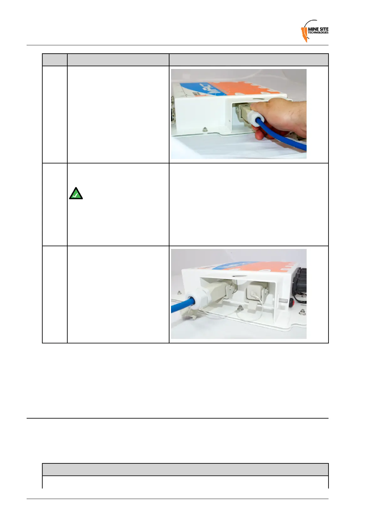
Note: If a NS50 is installed
at the other end of the
downstream cable, the bre
link LED will light up green.
The bre activity LED will
ash with network activity.
Slide the retention arm back into the
unit and screw the locking nut tight.
7
Connecting a NS50 to a branch NS50 requires simply connecting composite cables to the additional bre
ports. The connected bre ports will cause the corresponding bre port LEDs to become active. If you
are adding NS50 units to an existing system, please consult your MST System Engineer to ensure power
requirements are being met.
3.7 Standard Composite and Fibre Cable Lengths
While custom cable runs can be made where necessary, it is faster and cheaper to use the following
standard cable lengths supplied by MST:
Table 1: Composite Cable
Composite Cable LengthPart Number
80mW-CFC-006-T80
Revision C34NS50 User Guide
Installation

 Loading...