Discharge Chute and Controls (Joystick, Hex Shaft)
117
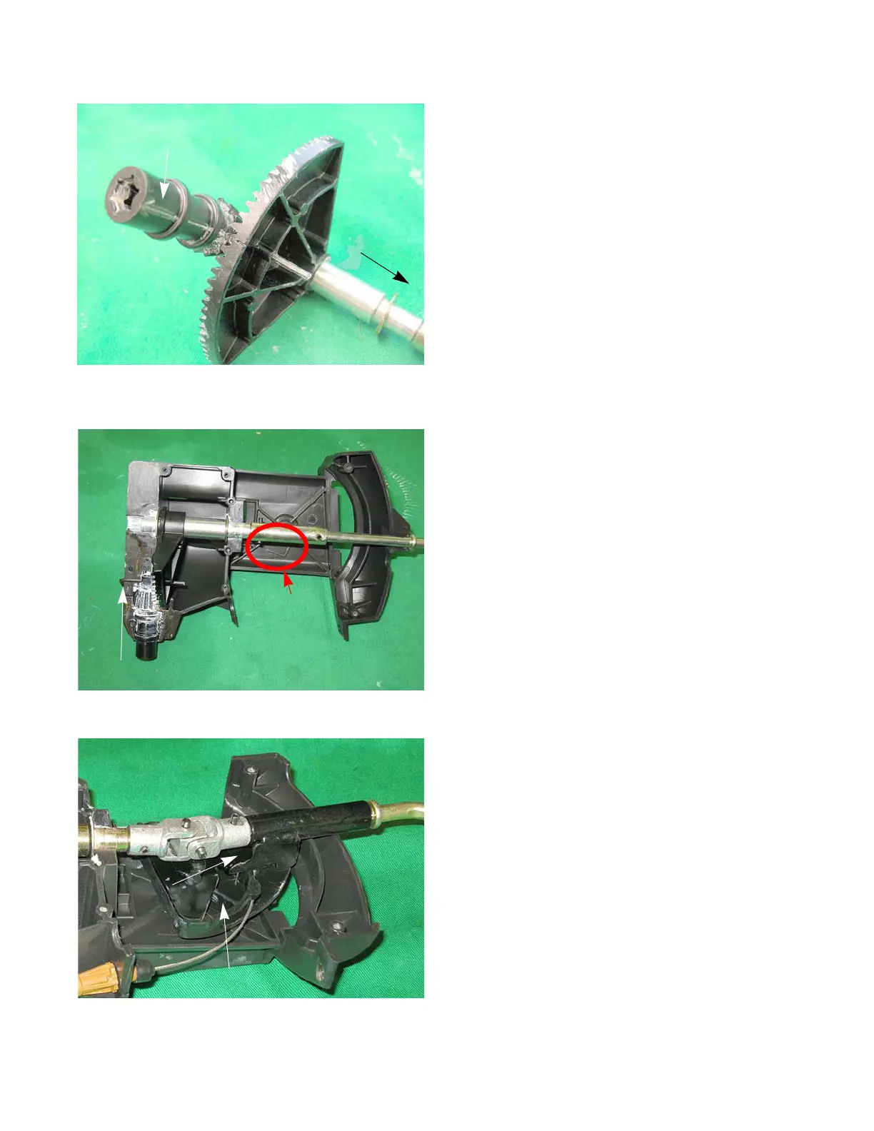
5. Pin the Pinion Gear to the Sector Gear with a 1/8”
hex key, so that the arrow on the Pinion Gear is fac-
ing the handle. See Figure 10.34.
6. Set the Pinion Gear, Sector Gear and shaft into the
left housing with the hex key still in place.
NOTE: The left housing has a “L” on it. See Figure 10.35.
NOTE: On 4-way units, insure that the stud on the shaft
passes through the Cable Guide and the housing.
See Figure 10.36.
NOTE: The tab of the Cable Guide must be seated in the
notch in the bracket on the shaft. See Figure
10.36.
7. Lubricate all friction surfaces with Renolit Polar
Grease part number 937-04085.
Figure 10.35
L
Key hangs over edge of housing
Figure 10.36
Cable guide
Notch and tab
 Loading...