Configuring the job computer
Selecting and configuring the speed sensor
If the “Speed source” parameter does not appear on the “Speed” screen, and the speed signal should
be received through the ISOBUS, proceed as follows:
The speed signal can be received through the ISOBUS.
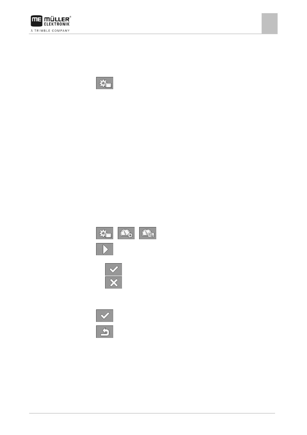
1. Switch to the “PARAMETERS” screen:
2. Set the “Wheel impulses” parameter to “0”.
Calibrating the speed sensor with the 100m method
When calibrating the speed sensor with the 100m method, you determine the number of impulses
received by the speed sensor in a distance of 100m. When you know the amount of impulses, the job
computer can calculate the current speed.
If you know the number of impulses for the wheel sensor, you can also enter this number manually.
You can enter different pulse values for up to three different wheels.
Wheel sensor, radar sensor or GPS speed sensor is installed on the field sprayer.
A distance of 100m has been measured and marked. The distance must correspond to the field
conditions. It should therefore lead over a meadow or a field.
The tractor with connected implement is ready for a 100m drive and is at the start of the marked
distance.
1. Ensure that all prerequisites have been fulfilled.
2. Switch to the “CALIBRATION – wheel impulses” screen:
> >
3. - Start calibration.
⇨ The following function icons appear:
- Stop calibration.
- Abort calibration.
4. Drive the previously measured 100m distance and stop at the end.
⇨ During the drive, the currently determined impulses are displayed.
5. - Stop calibration.
6. - Exit the screen.
⇨ The number of impulses appears on the “Wheel impulses” line
Configuring the reverse driving sensor
If the trailed implement or the tractor sends a reverse driving signal through the ISOBUS, the job
computer can use this signal to adjust its regulating behaviour when driving in reverse.
You can find more information in this section: Configuring automatisms when driving in reverse
The following signal sources are possible:
 Loading...