Mounting and installation
Installing the junction box
⇨
6. When the work is completed, separate the connection and screw the dust protection cap back
on.
⇨
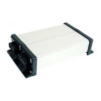
Installing the junction box
Take note of the following when selecting the installation location:
▪ Ensure that cables cannot be damaged by the moving implement.
▪ The cable glands must be facing downwards.
Connecting the sensors and actuators to the junction box
Every sensor and every actuator that is mentioned in the pin-out diagram must be connected to the
junction box mentioned in the pin-out diagram.
This can be done in two ways:
▪ The sensor or actuator ends with a short cable and an AMP connector.
In this case, you will receive a fitting extension cable for each sensor. You must insert the
extension cable in the junction box and connect it to the fitting terminal.
▪ The sensor or actuator ends with a long cable without a connector. You have to insert it in the
junction box and connect it to the fitting terminal.
The terminal to which you must connect the cable core depends on the respective implement and on
the type of sensor or actuator.
Please note that the cable cores for the ultrasonic sensor trigger always need to be connected to Pins
2 and 3.
Risk of short-circuit
When exchanging the polarity of cable cores, machine sensors can be damaged by a short-circuit.
◦ Pay attention to the polarity of the cable cores and the terminals.
1. Remove the cable coating so that all cable cores are exposed.
2. Insert the cable to the end of the coat. There should only be cable cores inside the junction box.
The cable coating must end at the junction box casing. This is the only way to ensure that you
have enough space in the junction box to be able to guide all of the cable cores to the terminals.
3. Remove the cable coating of the cable cores ca. 1 cm from the end of the cable core.
 Loading...