Configuring the job computer
Field sprayer with two circulations and job computers
⇨ The “ISO 11783” screen appears:
2. Configure parameter.
Geometry on a field sprayer with two job computers
You must measure and enter the following distances:
▪ On the main job computer: Distances between the main boom, the axle, and the attachment
point.
▪ On the auxiliary job computer: Distance between the main boom (CRP_2) and the auxiliary
boom.
On systems with a one-sided folding auxiliary boom [➙ 78], you must also enter the distance
DRP_Y:
▪ The boom is located only on the left side: 0cm
▪ Boom on the right side: Working width of the boom in cm
To enter the sprayer geometry in the main job computer:
You have set the second connector on the main job computer.
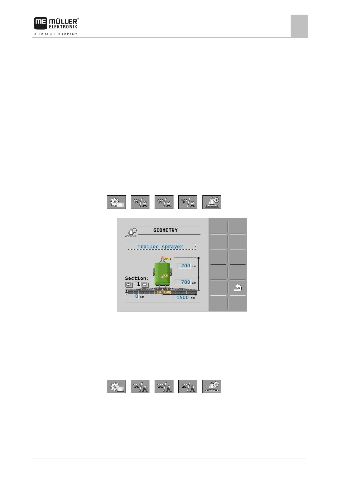
1. Switch to the “Geometry” screen in the application of the main job computer:
> > > >
⇨ The following screen appears:
⇨ There are two red dots on the diagram: CRP_1 - Attachment point; DRP - Axle; CRP_2 -
Work point of the main boom. You must also measure the distance from this point to the
second boom later.
2. On the line above the drawing, set the corresponding sprayer type.
3. Enter the measured values.
To enter the sprayer geometry in the auxiliary job computer:
1. Switch to the “GEOMETRY” screen in the application of the auxiliary job computer:
> > > >
 Loading...