Do you have a question about the Muller Elektronik TRACK-Guide III and is the answer not in the manual?
Core safety guidelines for product use, maintenance, and general precautions.
Defines the proper application and operational scope of the display unit.
Details the software applications installed and available for the display unit.
Step-by-step guide for connecting the display unit to the vehicle's power source.
Instructions on establishing an ISOBUS connection for power and communication.
Outlines the initial steps and configurations required after powering on the display.
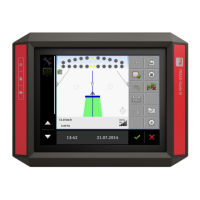
Explains how to configure and utilize the display for parallel guidance operations.
Covers the process of connecting and setting up various GPS receivers with the display unit.
Detailed steps for physically connecting a GPS receiver to the display unit.
Instructions on selecting and activating the correct software driver for the GPS receiver.
Explains how to adjust internal settings and parameters of the connected GPS receiver.
Instructions for connecting various sensors, like work position sensors, to the display.
Steps for connecting analog cameras, including HQ models, to the display.
Manages the activation and deactivation of installed software applications or plugins.
How to create, activate, and manage profiles for different tractors.
Procedures for calibrating the vehicle's speed sensor for accurate measurements.
Steps to calibrate analog sensors for detecting implement working position.
Configuration of the tractor's dimensions for accurate implement positioning.
Creation and management of virtual job computers for non-ISOBUS implements.
Configuration options for virtual job computers, including implement type and external controllers.
Setup and configuration of the ISOBUS-TC application for task management.
Defines how ISOBUS-TC operates, controlling task management and data processing.
Manages the list of connected ISOBUS job computers for data exchange.
Manages field data, including creating, importing, and exporting SHP files.
Guides on importing field boundary and data files in SHP format.
Information on loading and using prescription maps for variable rate application.
Process for importing prescription maps in shapefile format.
Details the pinout and signal functions for Port A (CAN bus).
Explains the possible uses and pin assignments for Port B.
| Brand | Muller Elektronik |
|---|---|
| Model | TRACK-Guide III |
| Category | Automobile Electronics |
| Language | English |