EasyManuals Logo

Muller Elektronik TRACK-Guide III User Manual

Muller Elektronik TRACK-Guide III
86 pages
To Next Page IconTo Next Page
To Previous Page IconTo Previous Page
Page #80 background imageLoading...
Page #80 background image
12
Technical specifications
Assignment plans
80
V9.20191001
31302713-02-US
Purpose
Pins used
As second CAN interface
7, 9
As second serial interface
2, 3, 4, 5
As signal input for two digital and one analogue
signal.
1, 5, 6, 8
Pin
Signal name
1
Wheel sensor
1
6
PTO
2
2
/RxD2
7
CAN2_H
3
/TxD2
8 Working position sensor
3
or
Reverse signal for determining the course
4 Voltage supply for GPS receiver
Switched input voltage, ≤ 250mA
9
CAN2_L
5
GND
Screen
ESD/EMC shielding
Legend:
1
) Digital input as per: ISO 11786:1995 chapter 5.2
2
) Digital input as per: ISO 11786:1995 chapter 5.3
3
) Analog input as per: ISO 11786:1995 chapter 5.5
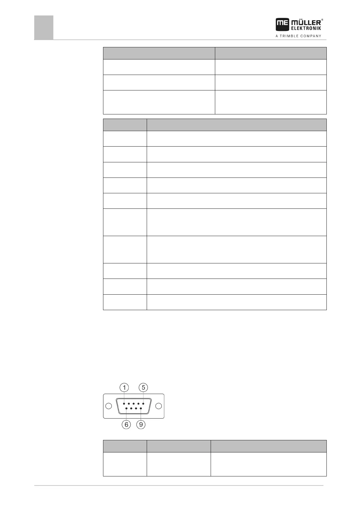
Port C
9-pin Sub-D connector
Pin
Signal name
Function
1 (DCD1) Switched input voltage ≤ max. 250 mA total (Pin 1
+ Pin 4)
12.2.3

Table of Contents

Questions and Answers:

Question and Answer IconNeed help?

Do you have a question about the Muller Elektronik TRACK-Guide III and is the answer not in the manual?

Muller Elektronik TRACK-Guide III Specifications

General IconGeneral
BrandMuller Elektronik
ModelTRACK-Guide III
CategoryAutomobile Electronics
LanguageEnglish