User Manual
When decoding, if "Parity" is not set to "None", and the check bit error is
detected, two red error marks will be displayed in the corresponding position in
the waveform.
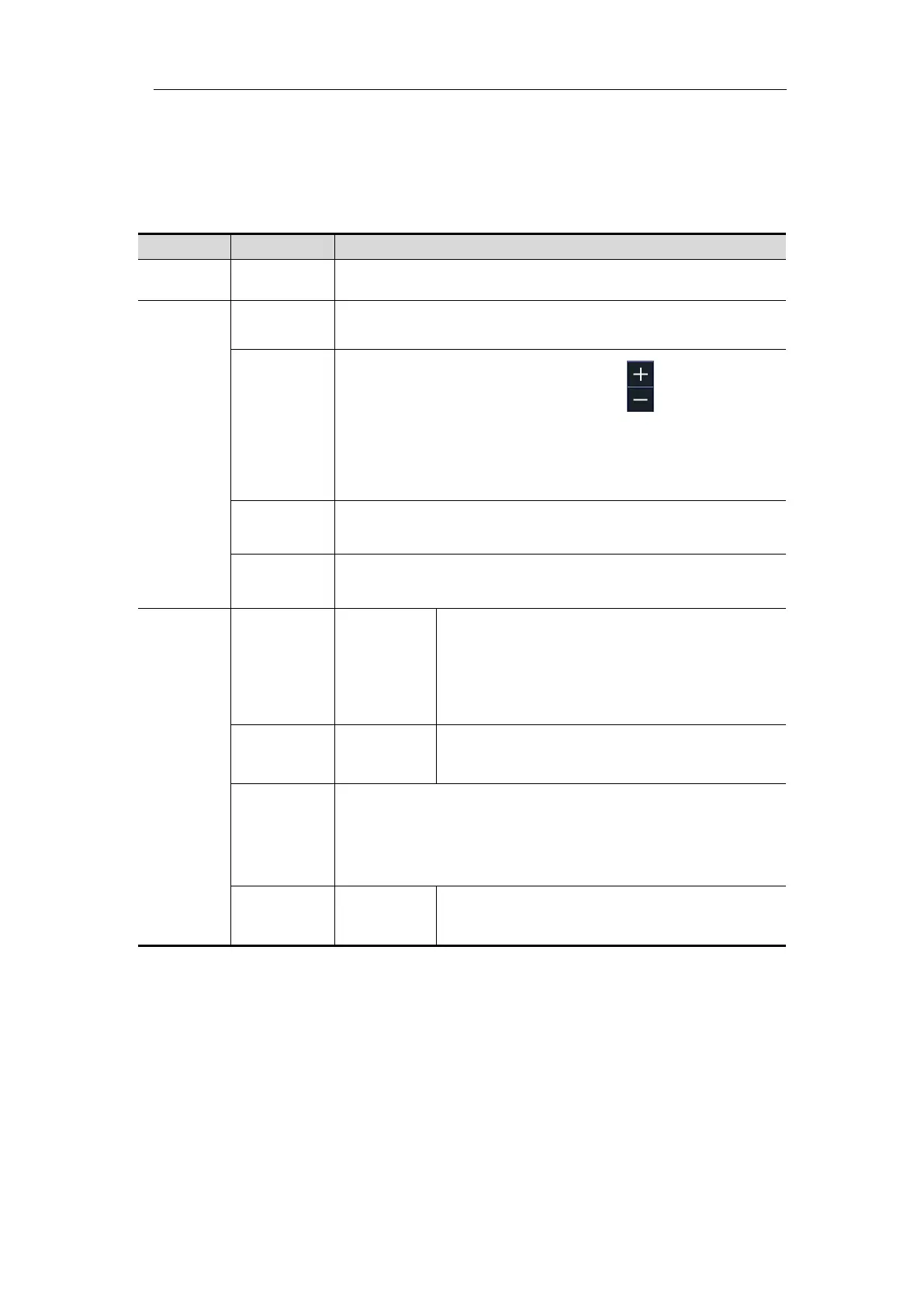
RS232 Decoding menu list:
Set bus type of decoding as RS232.
Turn the M rotary control to select from the Baud list on
the left.
Turn the M rotary control (or tap on in touchscreen)
to set the Baud. The range is 50 to 10,000,000.
Tip: You can select the nearest value in Common Baud,
and then adjust it in this menu.
Set the data width of each frame to match the signal. It
can be set to 5, 6, 7 or 8.
set the even-odd check mode to match the polarity used
by the signal.
Set the display format of the bus.
Select "ON" to display the event table.
If a USB storage device is currently connected to the
instrument, save the event table data in a .csv
(spreadsheet) formatted file on the external USB storage
device.
Select "ON" to display the ASCII table.
2. I2C Decoding
To decode I2C signal:
(1) Connect the clock line (SCLK) and the data line (SDA) of the I2C signal to the
Signal Input Channels of the oscilloscope.
(2) Adjust to the proper time base and voltage division.
(3) In trigger menu, select Bus trigger, and select bus type as I2C, set parameters
based on the characteristics of the signal, trigger the signal correctly and obtain
stable display. Refer to "I2C Trigger" on page 51.