Chapter 2 – Installing and Cabling the MultiVOIP
12 MultiVOIP® Voice/Fax over IP Gateways
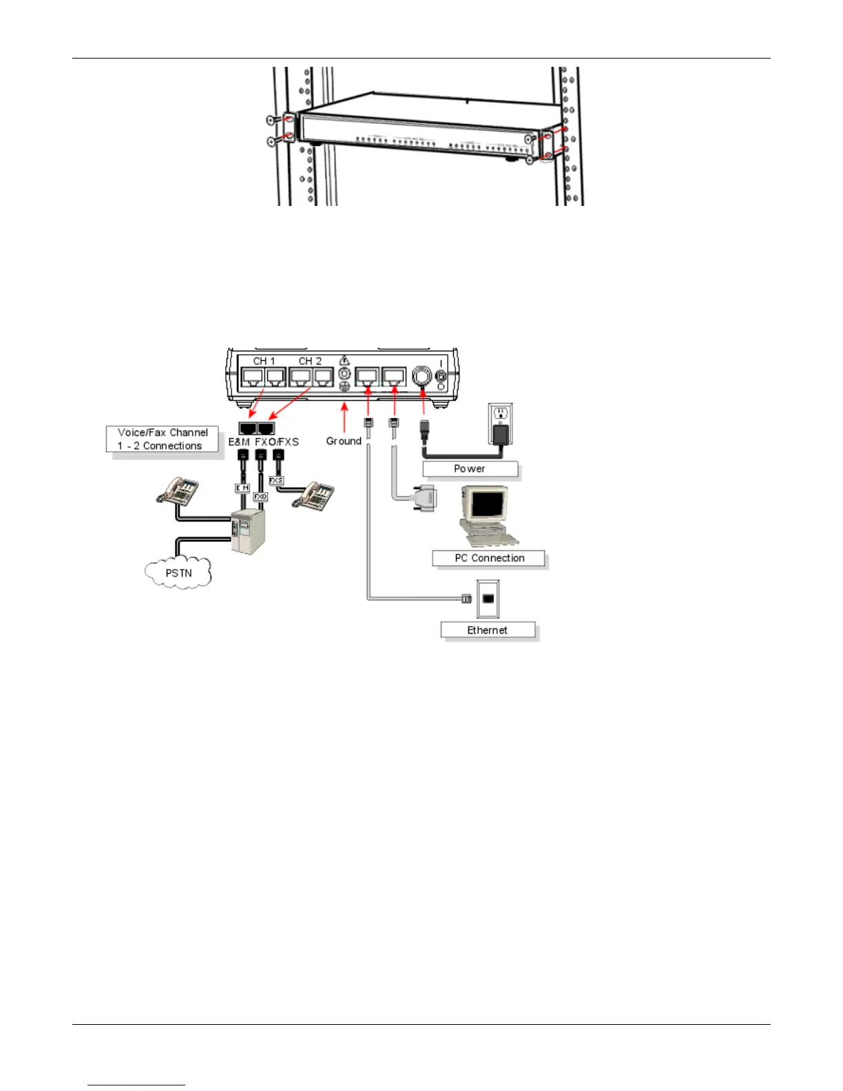
Connecting the MVP210 to LAN and Telephone Equipment
To connect the MultiVOIP unit to your LAN and telephone equipment:
1. Connect the power cord supplied with your MultiVOIP to the power connector on the back of the MultiVOIP
and to a live AC outlet as shown in the figure that follows.
Note: The –SS and –FX models do not have the E&M jacks as shown.
2. Connect the MultiVOIP to a PC by using a RJ-45 (male) to DB-9 (female) cable. Plug the RJ-45 end of the
cable into the Command port of the MultiVOIP and the other end into the PC serial port.
3. Connect a network cable to the ETHERNET 10/100 connector on the back of the MultiVOIP. Connect the
other end of the cable to your network.
a. For an FXS or FXO connection (-SS and -FX series).
(FXS Examples: analog phone, fax machine |
FXO Examples: PBX extension, POTS line from telco central office)
Connect one end of an RJ-11 phone cord to the Channel 1 FXS/FXO connector on the back of the
MultiVOIP. Connect the other end to the device or phone jack.
b. For an E&M connection.
(E&M Example: trunk line from telephone switch)
Connect one end of an RJ-45 phone cord to the Channel 1 E&M connector on the back of the MultiVOIP.
Connect the other end to the trunk line.
Verify that the E&M Type in the E&M Options group of the Interface dialog box is the same as the E&M
trunk type supported by the telephone switch. See Appendix B for an E&M cabling pin-out.