Appendix C—Installing an MVP428 Upgrade Card
MultiVOIP® Voice/Fax over IP Gateways 147
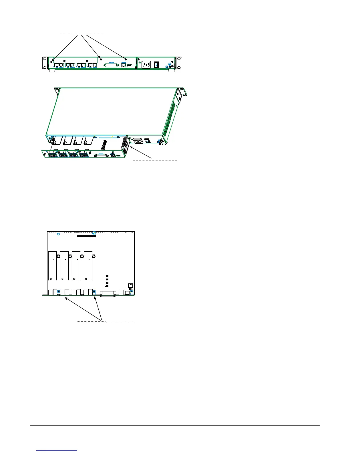
4. Slide the main circuit board out of the chassis far enough to unplug the power connector.
5. Unplug the power connector from the main circuit board.
6. Slide the main circuit board completely out of the chassis and place on a non-conductive, static-safe
tabletop surface.
7. Remove mounting hardware (2 screws, 2 nuts, and 4 standoffs) from its package.
8. On the phone-jack side of the circuit card, three screws attach the circuit card to the back panel. Two of
these screws are adjacent to the four phone-jack pairs. Remove these two screws.
9. Replace these two screws with standoffs.
back panel screws (3)
power connector
Screw locations (2)
at phone-jack edge
of board.