Troubleshooting
22 AP-74700 – Rev. 1.0 – 10/03/2008
If anything goes wrong in this process, the following parts inside this loop needs to be verified:
1) Check the encoder sensor
Go to diagnostics Æ test Æ encoder
If the Hex counter changes near CR_ENC, when moving the carriage, the encoder signal is OK. To be able
to move the carriage freely, the front cover (incl. cover sensors) must be opened.
2) Check the cover switches + connectors
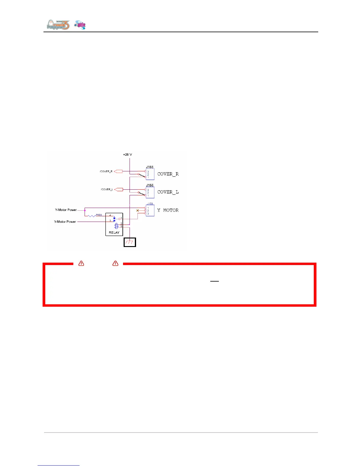
The cover switches make contact with a relay. This relay physically connects/disconnect the Y-motor from
the Y-motor power circuitry. Pin 1 and 2 will measure 0 ohms.
If one of both cover switches are open, the relay will disconnect. Instead the cover switch must close
contacts 2 and 3. In this way the /COVER-detection lines integrated inside the electronics, will recognise
that the cover is open and inform the operator.
• Check if the connector J156 is bridged
between pin 1 and 2 on the mainboard
(applicable for SPFR100 only)
• Make sure J155 is properly connected to
the cover switch
Important
• 28 Volts is directly connected to the cover switches! Therefore the switches are properly
insulated. Be aware removing the covers, the chassis is not touching the insulation and
breaking so it hits the contacts. This will result in a broken main board!
• Shutting-down the printer while removing the covers is strongly recommended!
The sensor can also be checked via the “test sensor” inside diagnostics.
3) Check the relay RY1 on the mainboard
On the picture, you can see that the relay can switch the Y motor on/off. If the cover is being closed (= both
switches closes too), you should hear the relay clicking.
If the relay RY1 is NOT clicking after closing, verify if the cover switch is really closed. Measure pin 1 and 2
of the connector of J155 and J156. Both pins should be 0 ohms!
If the switches are OK, the relay or the driver of the relay on the mainboard might be is broken. In that case
replace the mainboard