VS1 Operations and Maintenance Manual Operating the transmitter
Issue 3.1 2013-10-01 Page 2-153
Use the up and down buttons to select the desired digital output (1 through 16) from the list. Each
screen shows the current digital output parameter (e.g., RF On/Off), as well as the polarity (e.g., RF
On = Low) and current state (e.g., high, low) of the corresponding output pin. Use the right-arrow
button to enter the Selection/Polarity screen for the selected output to allow editing of the selection
or the polarity. Press cancel (
X) to return to the previous menu.
If you save a change to a digital output via the front panel UI, it will also be displayed on the AUI
page.
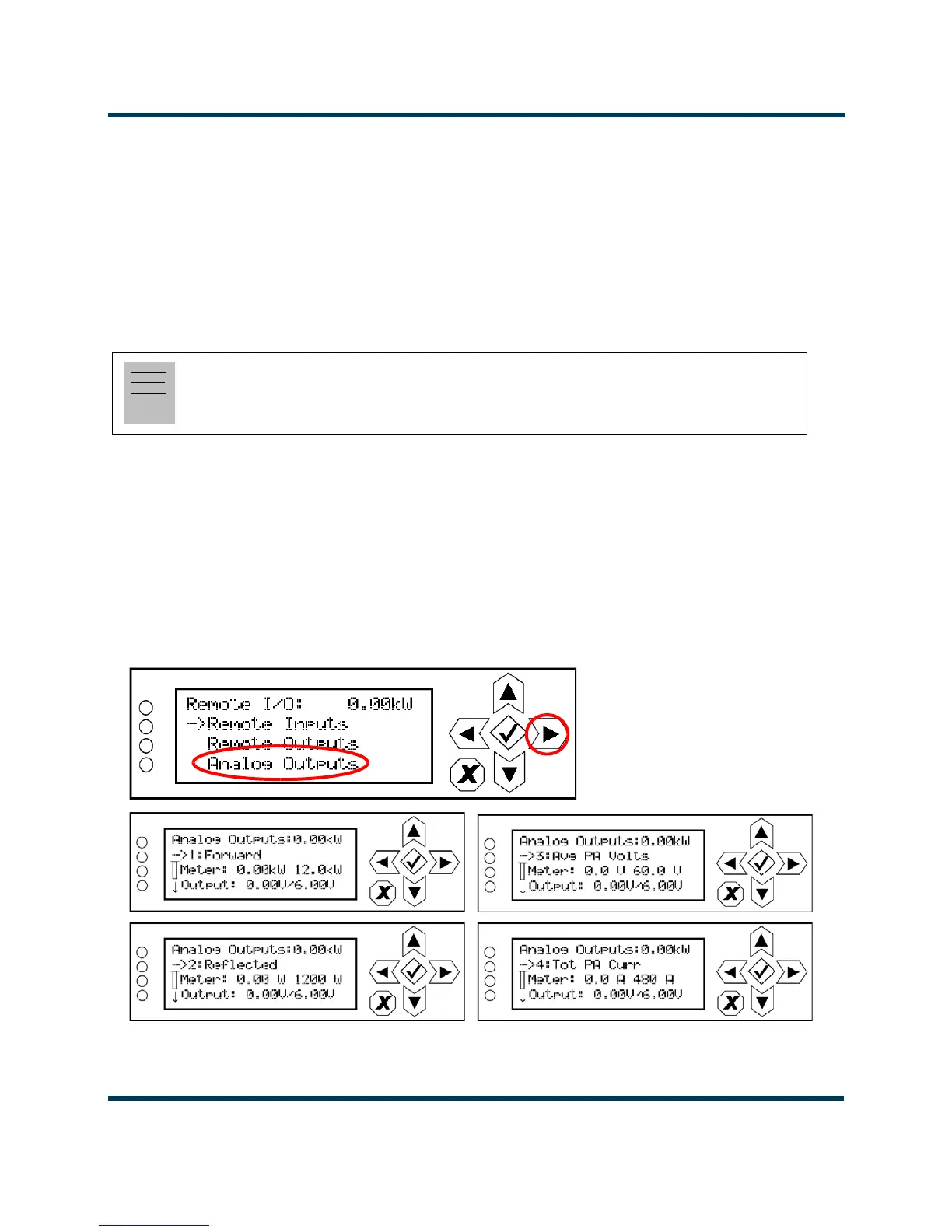
Analog Outputs - Front Panel
Using the
Analog Outputs screens (see Figure 2.137), you can view the levels of four pre-defined
analog outputs that are representative of critical transmitter parameters.
Nautel sets analog output defaults prior to shipping. There are no configuration options. They are for
monitoring purposes only. See the VS1 Pre-installation Manual for details.
Figure 2.137: Analog Outputs Screens
Note:
The selection and polarity options for digital outputs are the same as described in Select output
channel - AUI on page 2-148 and Configure output control logic - AUI on page 2-148.