VS1 Operations and Maintenance Manual Operating the transmitter
Page 2-42 Issue 3.1 2013-10-01
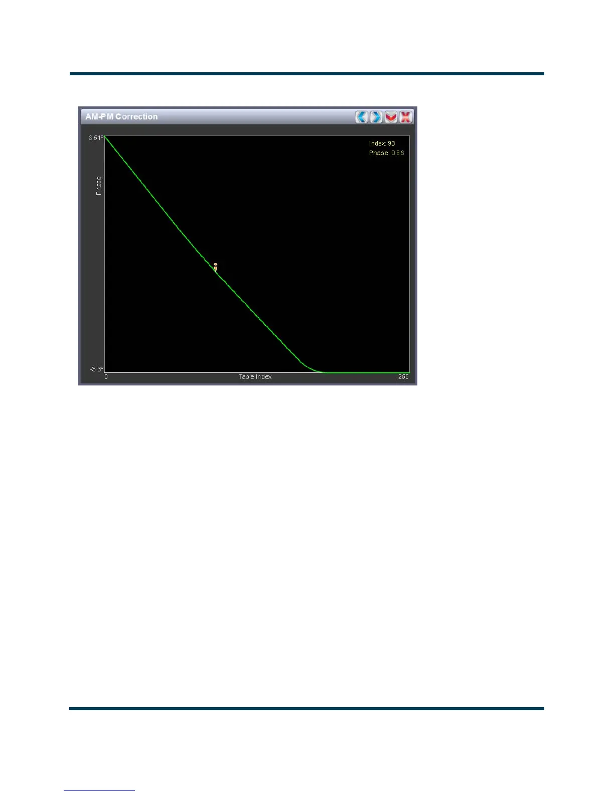
Figure 2.29: AM-PM Correction
AM-PM correction
This panel displays the phase correction being applied to the RF drive signal. The x-axis represents
the signal amplitude and the y-axis represents the phase shift correction applied for a given amplitude
value.
Click on the panel to display a cursor in the approximate area. The cursor position (phase and LUT
index) is noted in the upper, right-hand corner of the panel. Click in other areas of the instrument to
provide a coarse adjustment of the cursor position.
Use the left and right buttons as fine adjustments.
Use the up or down button to maximize (if it was minimized) or minimize (if it was maximized) the
panel size.